Vehicle fuel system

a fuel system and vehicle technology, applied in the direction of functional valve types, operating means/releasing devices of valves, machines/engines, etc., can solve the problems of increasing the complexity and cost of the vehicle fuel system, mechanical float valves that do not provide repeatable fuel fill levels, etc., and achieve the effect of increasing the usable volum

Active Publication Date: 2005-12-22
TI GRP AUTOMOTIVE SYST LLC
View PDF17 Cites 64 Cited by
  • Summary
  • Abstract
  • Description
  • Claims
  • Application Information

AI Technical Summary

Benefits of technology

[0008] Some potential objects, features and advantages that may be achieved by at least some of the presently preferred embodiments of this invention include providing a fuel system with an electrically operated vent valve for controlled venting of the fuel tank, controlled filling of the fuel tank, repeatable and accurate maximum fill level control, is programmable to meet individual vehicle platform specifications, enables an increased usable volume for fuel in the fuel tank, can make real time adjustments in response to environmental factors such as pressure, temperature, engine duty cycle, vehicle accelerations, vehicle inclination and fuel level, prevents liquid fuel flow to a fuel vapor canister, prevents fuel from exiting the fuel tank during a vehicle rollover, is of relatively simple design, economical in manufacture and assembly, and in service has a long useful life.

Problems solved by technology

With the fill limit valve closed it is no longer possible to vent the fuel tank and the pressure inside the tank increases, thereby causing liquid fuel to back-up in a fill tube which actuates an automatic shut-off of a vehicle refueling pump nozzle and terminates the flow of fuel into the tank.
As a result, a mechanical float valve suitable for one fuel tank may not be suitable for another.
In addition, generally, mechanical float valves do not provide a repeatable fill level of fuel within the tank from one fill sequence to another.
Having separate valves performing individual functions adds to the complexity and cost of the vehicle fuel system.

Method used


Image

  • Vehicle fuel system
  • Vehicle fuel system
  • Vehicle fuel system

Examples


Embodiment Construction

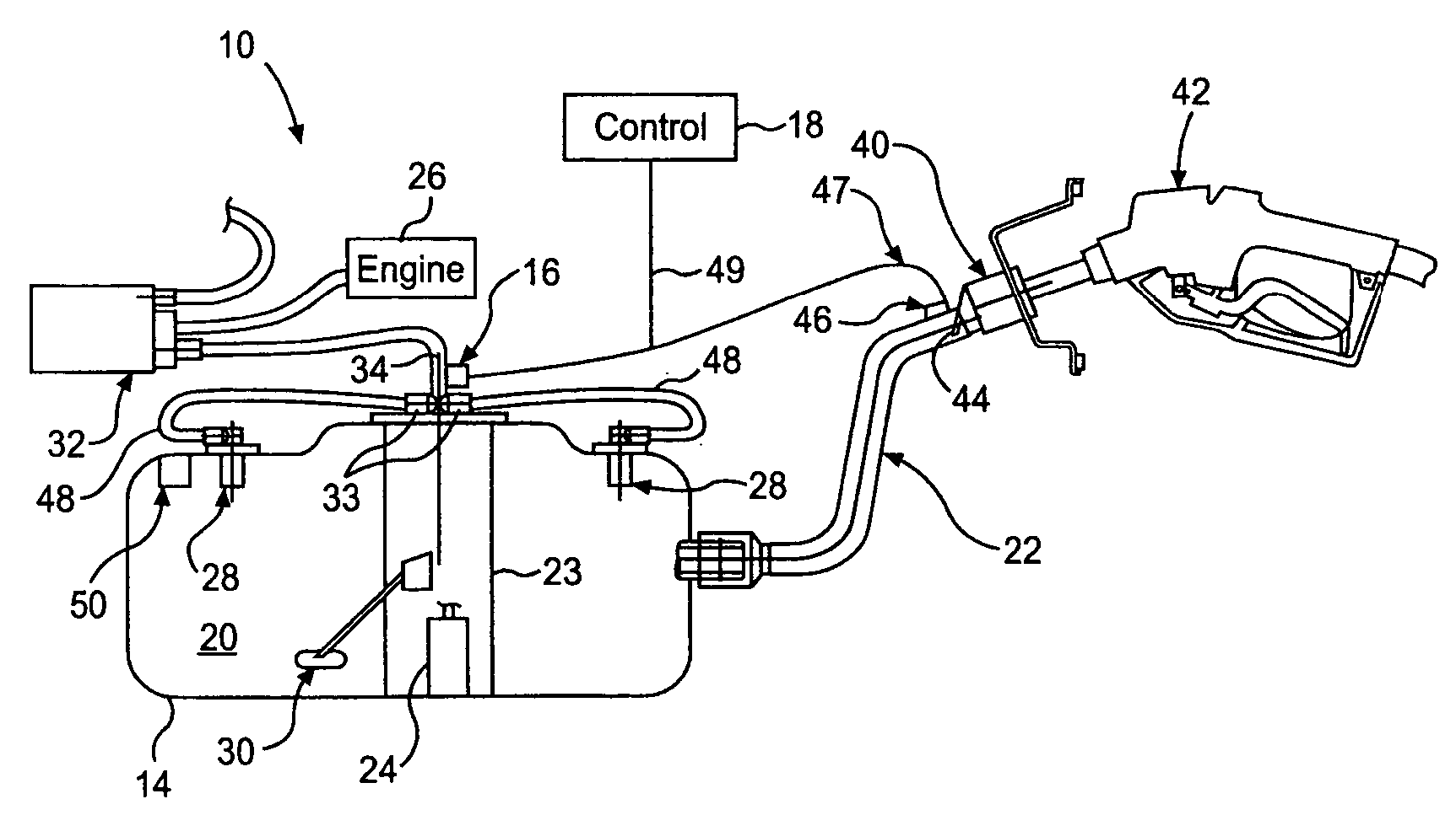
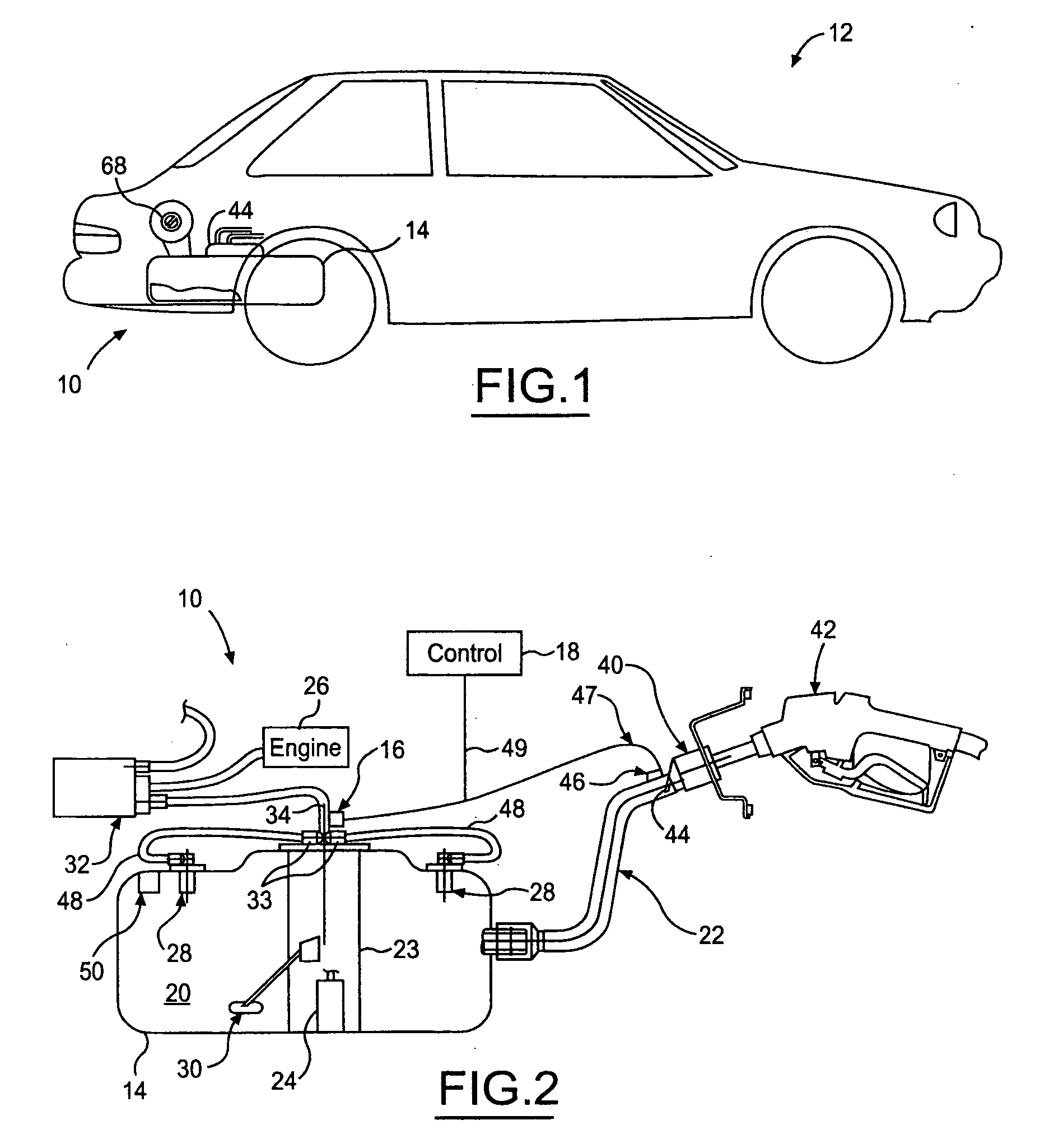
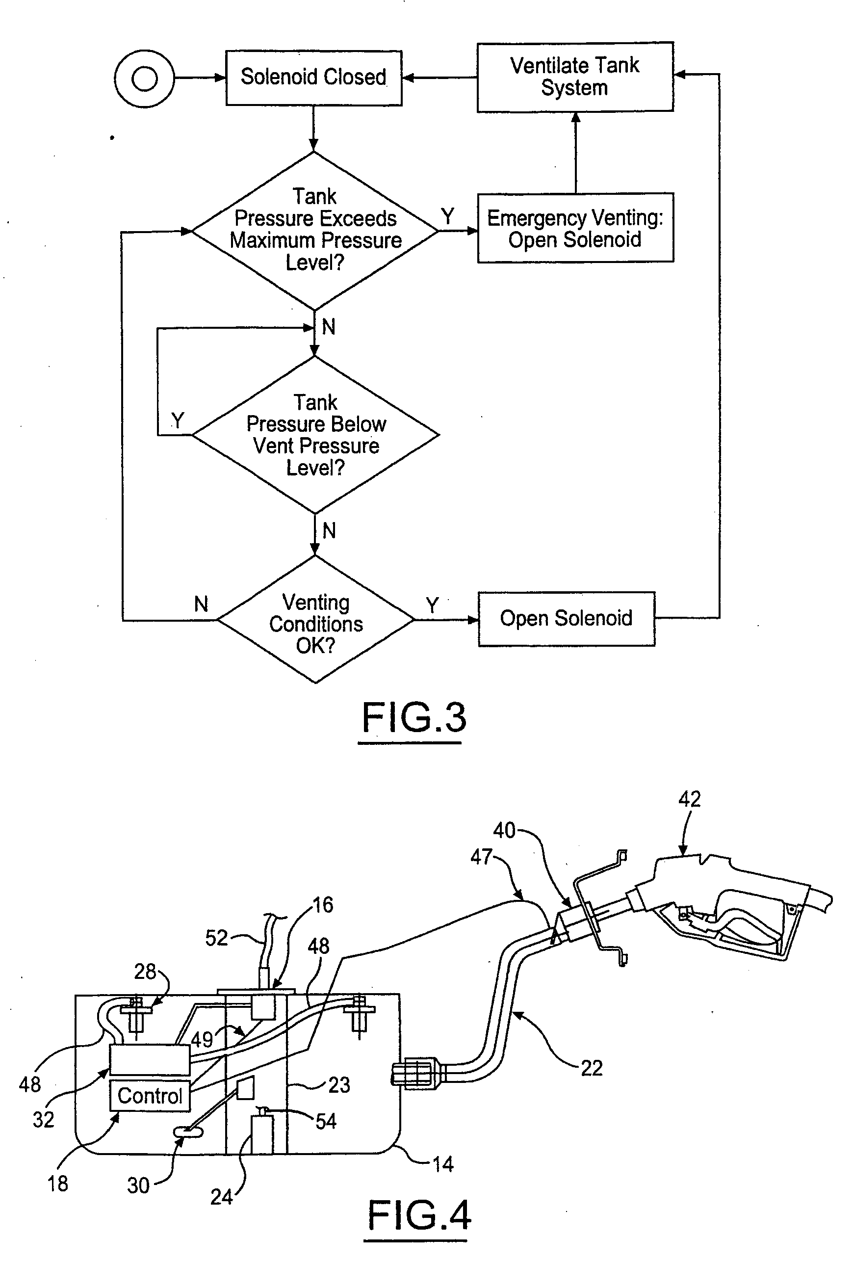
[0024] Referring in more detail to the drawings, FIGS. 1 and 2 illustrate a fuel system 10 constructed according to one presently preferred embodiment of this invention for a vehicle 12 having a fuel tank 14 and at least one electrically operated vent valve 16 (EOVV 16) to control the release of fuel vapor from the fuel tank 14. The EOVV 16 can be actuated by a controller 18 that monitors and / or is responsive to a plurality of conditions within and outside of the fuel tank 14. For example, the controller 18 may be responsive to a refueling event wherein fuel is added to the fuel tank 14 to open the EOVV 16 and allow fuel vapor to be displaced from the fuel tank. The controller 18 may also be responsive to internal fuel tank pressure to open when a threshold pressure is reached within the tank 14 to limit the maximum tank pressure. The controller 18 can also be responsive to various vehicle operational conditions such as vehicle acceleration (speeding up or hard braking, for example)...


PUM


Abstract

A fuel system with a fuel tank having at least one opening into an interior of the fuel tank, and an electrically operated vent valve having an inlet communicated with the interior of the fuel tank and an outlet for venting fuel vapor from the fuel tank. The vent valve is movable in response to an electric signal between an open position allowing fuel vapor through the outlet and a closed position to restrict fluid flow through the outlet. A controller is operably communicated with the vent valve to control application of an electric signal to the vent valve and thereby control at least in part the movement of the vent valve between its open and closed positions. In one embodiment the controller is responsive to a fill level in the fuel tank to control the position of the vent valve and thereby the fill level attained within the fuel tank.

Description

REFERENCE TO RELATED APPLICATION [0001] Applicant claims priority of U.S. provisional patent application Ser. No. 60 / 582,009, Filed Jun. 22, 2004.FIELD OF THE INVENTION [0002] This invention relates generally to vehicle fuel systems, and more particularly to devices controlling fuel flow in and vapor venting from a fuel tank. BACKGROUND OF THE INVENTION [0003] Fuel tanks within a fuel system of a vehicle have a generally fixed volume in which to maintain fuel. Generally, the maximum fill level for liquid fuel within the fuel tank is controlled by a mechanical shut-off valve that vents the fuel tank. Frequently, this valve is referred to as a fill limit valve. The fill limit valve typically has a float to open and close an orifice in the valve in response to the level of liquid fuel in the tank. When the float reaches a predetermined level indicating the desired maximum fuel level in the fuel tank, the fill limit valve is closed. With the fill limit valve closed it is no longer possi...

Claims


Application Information

Patent Timeline
Patent Type & Authority Applications(United States)
IPC IPC(8): B60K15/035F16K17/36F16K24/04F16K31/06
CPCB60K15/035F16K31/0655F16K24/04Y10T137/0777
Inventor ATWOOD, JEFFREY M.BRADY, DAVID A.FORGUE, JOHN R.HENSCHEL, MATTHIASJOHANSEN, MARK R.KLOESS, MICHAELKUPERUS, PETER P.STICKEL, MARTIN
Owner TI GRP AUTOMOTIVE SYST LLC
Why Eureka
Try Eureka