
Paint can extender

a paint can and extender technology, applied in the field of containers, can solve the problems of changing the thermal properties of paint, overflowing paint, and the small opening of the paint can that cannot provide a snug snap-fit connection, so as to reduce space and material, and achieve efficient configuration

Inactive Publication Date: 2012-02-02
RESOURCE PARTNERS ENTERPRISES
View PDF27 Cites 1 Cited by
  • Summary
  • Abstract
  • Description
  • Claims
  • Application Information

AI Technical Summary

Benefits of technology

[0007]This invention relates to a paint can pour spout and volume extending device. This device snuggly snap fits onto more than one sized opening in a paint can, thereby allowing the user to snuggly snap fit the device onto different sized paint cans. Multiple annular shoulders are disposed on the base of the device to allow a snap-fit connection between the device and the paint can, whereby each annular shoulder is sized to fit a particularly sized paint can opening. Furthermore, elements of each snap-fit connection have been overlapped and interconnected to reduce space and material, and thereby provide a more efficient configuration for forming the two snap-fit connections
[0009]The device of the present invention also increases the available volume of the paint can, whereby a user may apply a volume increasing agent to the paint without overflowing the paint. The cylindrical shape of the paint can is axially extended to provide for an increased volume capacity.
[0010]This extender device includes a broad pour spout which aids in pouring of the paint, and a looped portion for hanging the pour spout when not in use or to grasp the pour spout for movement.

Problems solved by technology

However, recently it has been discovered that after-market paint additives are desired by consumers which may change the thermal properties of the paint.
This leads to an overflowing of the paint when the additives are administered.
A larger or smaller diameter opening on the paint can cannot provide a snug snap fit connection as a necessary consequence of changing the diameter of the opening.

Method used


Image

  • Paint can extender
  • Paint can extender
  • Paint can extender

Examples


Embodiment Construction

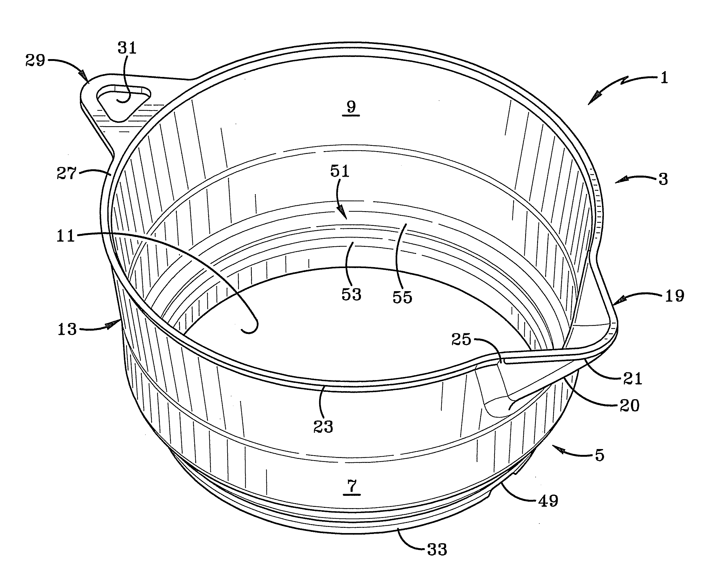
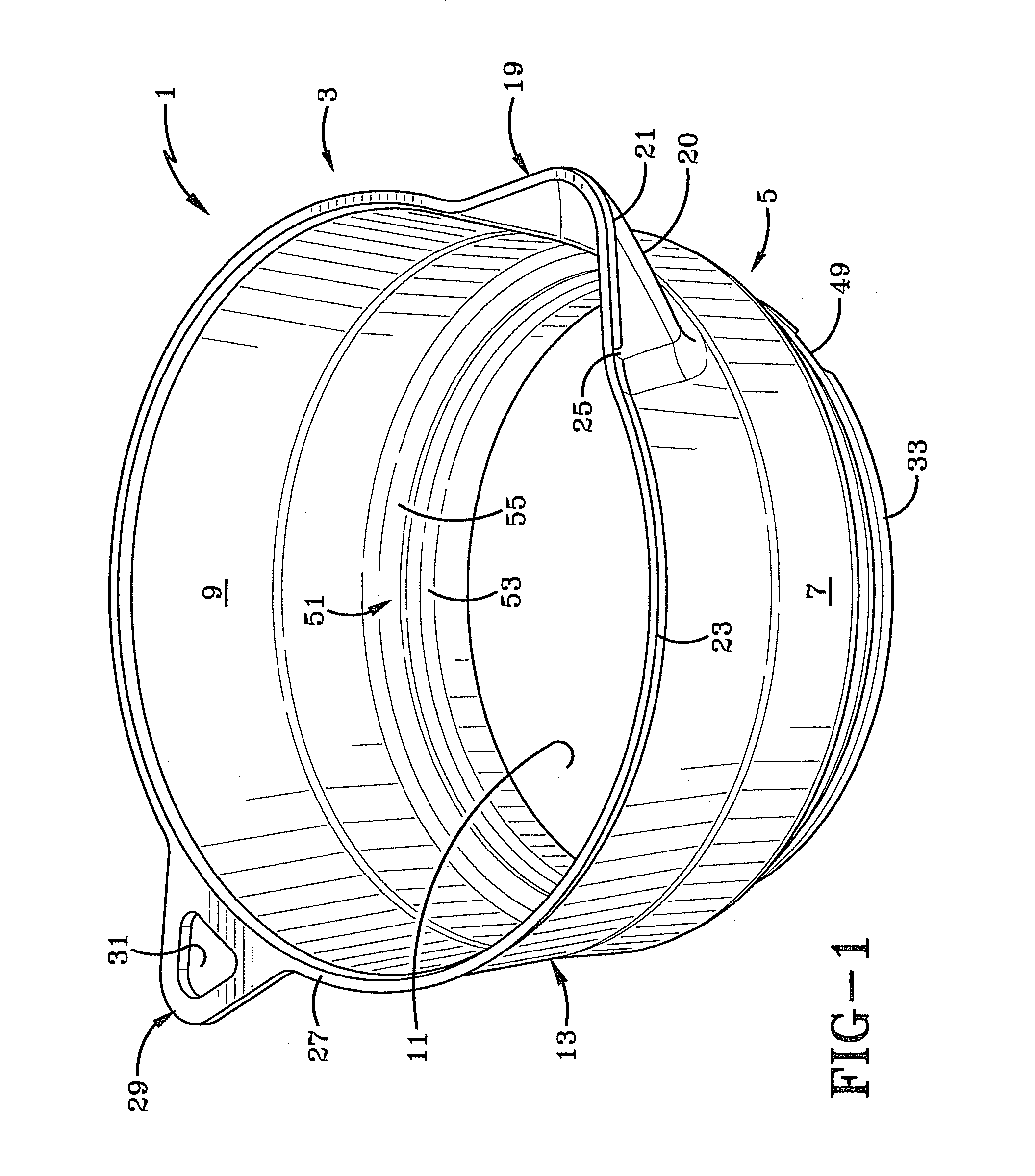
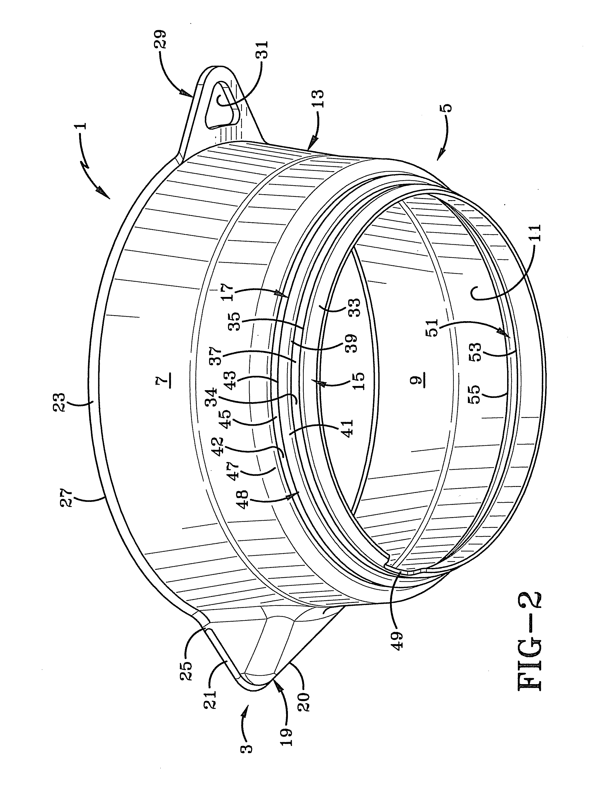
[0026]The paint can extender of the present invention is shown in FIGS. 1-13 and is indicated generally at 1. As shown in FIGS. 1-3, paint can extender 1 is integrally molded of a plastic material and is formed as a one-piece member, and has a generally cylindrical shape which includes an upper end 3, a lower end 5, an outer surface 7, and an inner surface 9 defining an inner channel 11 therethrough. A main body 13 extends from two annular stepped portions proximate lower end 5, whereby the two annular stepped portions define a first connection member 15 and a second connection member 17. Proximate upper end 3, main body 13 includes a pour spout 19 defined by an angled surface 20 and a pour lip 21.

[0027]As shown in FIGS. 1-4, main body 13 terminates proximate upper end 3 in a flared edge 23 which extends substantially around the periphery of the top-most portion of paint can extender 1 terminating at pour lip 21. Flared edge 23 is defined by the intersection of outer surface 7 and a...


PUM


Abstract

This invention relates to a device having a generally cylindrical main body defining an inner channel extending therethrough, a first connection member proximate one end of the device and a second connection member proximate the first connection member. The connection members are formed as annularly cantilevered snap-fit connectors, with each connection member sized to fit a particular opening in a container. Once engaged with the container, the contents may be poured through the inner channel and out through a pour spout formed distally from the connection members. An annular ring is disposed between each connection member and thereby defines an upper shoulder on the first connection member and a lower shoulder on the second connection member.

Description

CROSS REFERENCE TO RELATED APPLICATIONS[0001]This application claims priority from U.S. Provisional Application Ser. No. 61 / 368,916 filed Jul. 29, 2010; the disclosure of which is incorporated herein by reference.BACKGROUND OF THE INVENTION[0002]1. Technical Field[0003]This invention relates to containers for mixing and pouring substances contained therein. More particularly, this invention relates to selectively expanding the volume capacity of two differently sized containers. Specifically, this invention relates to a paint can extender which may removably snap-fit into two differently sized opening of two paint cans, thereby extending the cylindrical height of the paint can to allow a user to add and mix a volume increasing agent to the substance contained therein without overflowing the container.[0004]2. Background Information[0005]Heretofore, there have existed paint can pour spouts which attach to the opening of the paint can to allow a user to more easily pour the contents i...

Claims


Application Information

Patent Timeline
IPC IPC(8): B65D90/00
CPCB44D3/12
Inventor BOAL, JEREMY J.
Owner RESOURCE PARTNERS ENTERPRISES
Learn More