Method and system for fuel vapor control

a technology of fuel vapor and control method, which is applied in the direction of combustion air/fuel air treatment, machines/engines, engine starters, etc., can solve the problems of operator startled, insufficient vacuum for leak detection and purging routine, etc., and achieve the effect of reducing engine operation times

Active Publication Date: 2014-06-03
FORD GLOBAL TECH LLC
View PDF11 Cites 63 Cited by
  • Summary
  • Abstract
  • Description
  • Claims
  • Application Information

AI Technical Summary

Benefits of technology

[0007]In this way, an engine may be spun without fuel injection to generate a vacuum for evaporative leak diagnostics, while fuel tank vapors are isolated from the spinning engine by an auxiliary canister. By reducing the amount of fuel vapors drawn into the intake manifold during vacuum generation, air-to-fuel ratio deviations during a subsequent engine operation may be reduced. Also, by disabling the vacuum generation under specified engine-off conditions, the vehicle operator may not be alarmed.

Problems solved by technology

In hybrid vehicles, leak detection routines may be adapted to account for the reduced engine operation times which can lead to insufficient vacuum for leak detection and purging routines.
However, the inventors herein have identified potential issues with such an approach.
As another example, if the engine is spun to generate vacuum while the vehicle is stationary during fuel tank refueling, or while the vehicle operator is inspecting the vehicle, the operator may be startled.

Method used


Image

  • Method and system for fuel vapor control
  • Method and system for fuel vapor control
  • Method and system for fuel vapor control

Examples


Embodiment Construction

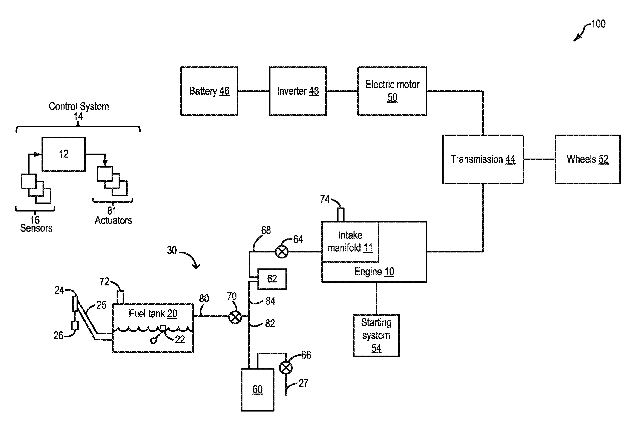
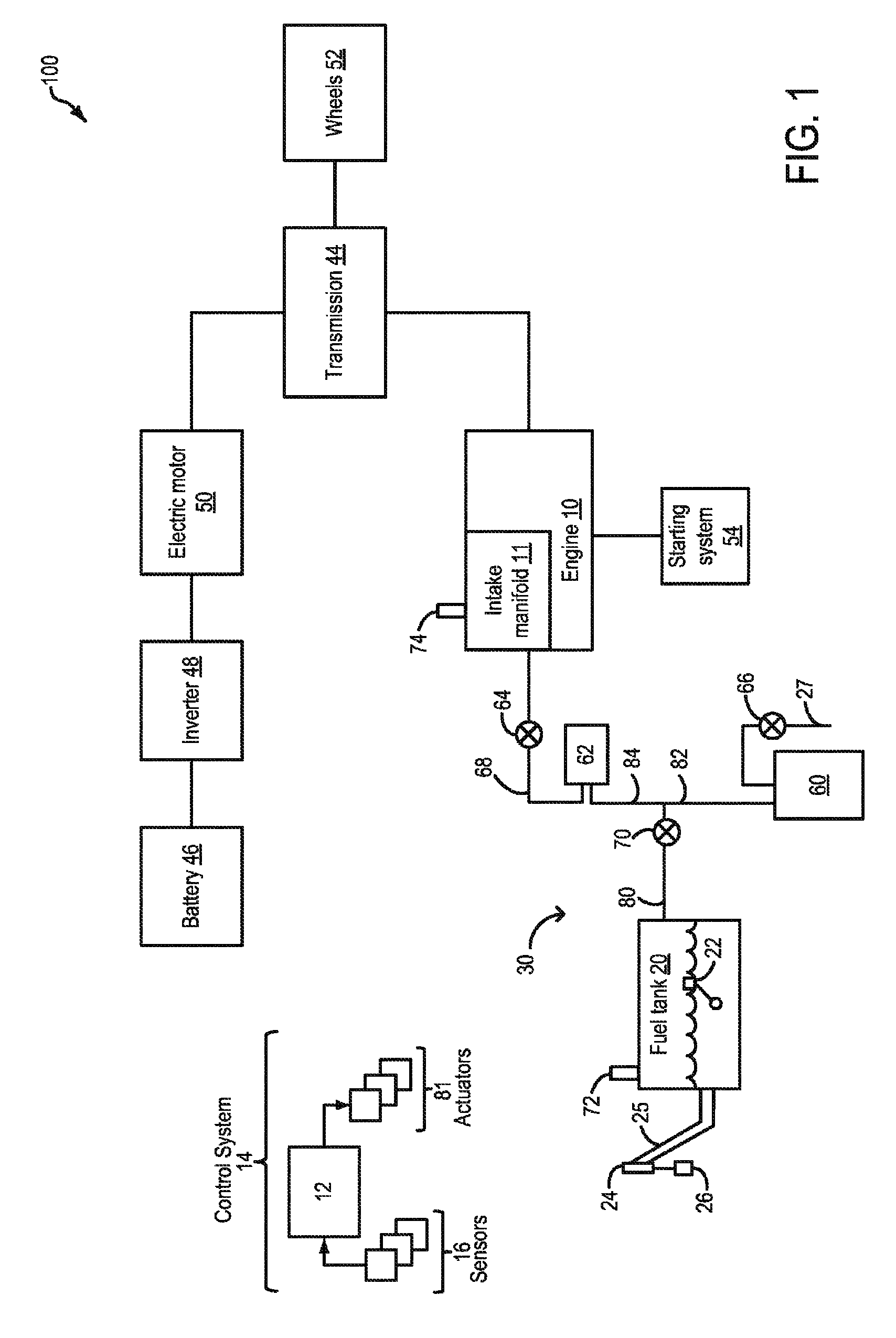
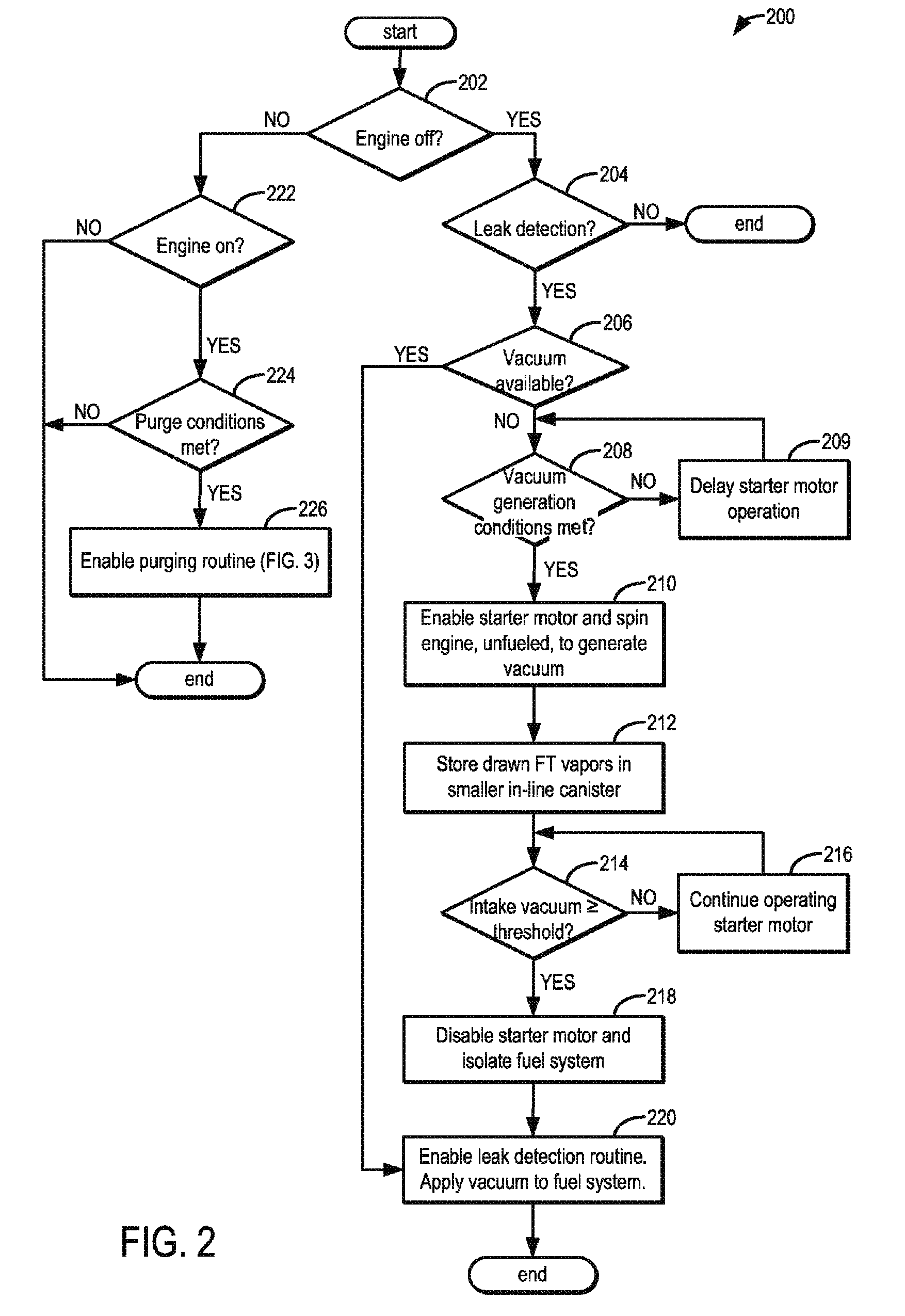
[0012]The following description relates to systems and methods for controlling an engine system coupled to fuel system, such as the system of FIG. 1. An unfueled engine is spun during selected vehicle key-off conditions to generate vacuum for a subsequent leak detection routine. An engine controller may be configured to perform a control routine, such as the routine of FIG. 2, to operate an engine starter motor to spin the engine, unfueled, and generate an amount of vacuum. Fuel vapors drawn from the fuel tank during the spinning are retained in a smaller in-line canister. Once a threshold amount of vacuum has been generated, the engine spinning is stopped, and the fuel system is sealed to perform a leak detection routine. Any fuel vapors retained in the smaller canister are purged in coordination with the purging of a main, larger canister of the fuel system during purging conditions, as elaborated in FIG. 3. By performing the leak detection during static conditions wherein noise f...


PUM


Abstract

Methods and systems are provided for operating an engine to generate vacuum for a subsequent leak detection routine. During a selected key-off condition, a starter motor is operated to spin the engine unfueled and generate intake vacuum for the leak detection. Fuel vapors drawn during the spinning are stored in an auxiliary canister that is purged along with a main canister during purging conditions.

Description

FIELD[0001]The present application relates to fuel vapor purging in vehicles, such as hybrid vehicles.BACKGROUND AND SUMMARY[0002]Vehicle emission control systems may be configured to store fuel vapors from fuel tank refueling operations and diurnal engine operation, and then purge the stored vapors during a subsequent engine operation. In an effort to meet stringent federal emissions regulations, emission control systems may need to be intermittently diagnosed for the presence of leaks that could release fuel vapors to the atmosphere. Evaporative leaks may be identified by sealing off the emission control system after generating a vacuum therein, and then monitoring the vacuum bleed-up. In hybrid vehicles, leak detection routines may be adapted to account for the reduced engine operation times which can lead to insufficient vacuum for leak detection and purging routines.[0003]One example approach for detecting evaporative leaks in a hybrid vehicle is shown by Chung et al. in U.S. P...

Claims


Application Information

Patent Timeline
Patent Type & Authority Patents(United States)
IPC IPC(8): F02M1/00
CPCF02N11/003B60K15/03504F02M25/0809B60K2015/03514F02M25/089B60W10/06B60K15/03519
Inventor JENTZ, ROBERT ROYPETERS, MARK W.DEZELIA, ANN IRENEDUDAR, AED MOHAMMAD
Owner FORD GLOBAL TECH LLC
Why Eureka
Try Eureka