Protection barrier system

a technology of protection barrier and locking pin, which is applied in the direction of roadway safety arrangements, roads, construction, etc., can solve the problems of insufficient the first barrier end post or the locking pin may not fit into the inadequately mated second end slot or hole, and the risk of intrusion into the occupation area of workers

Inactive Publication Date: 2005-03-08
SAFETY BARRIERS
View PDF28 Cites 94 Cited by
  • Summary
  • Abstract
  • Description
  • Claims
  • Application Information

AI Technical Summary

Problems solved by technology

A vehicle can penetrate through a line of prior safety barriers at any uncoupled end junction upon impact at or near the end junction, with a significant risk of intrusion into a worker occupied area.
If the supporting surface is uneven, such as broken pavement, the first barrier end post or locking pin may not fit into an inadequately mated second end slot or hole.

Method used


Image

  • Protection barrier system
  • Protection barrier system
  • Protection barrier system

Examples


Embodiment Construction

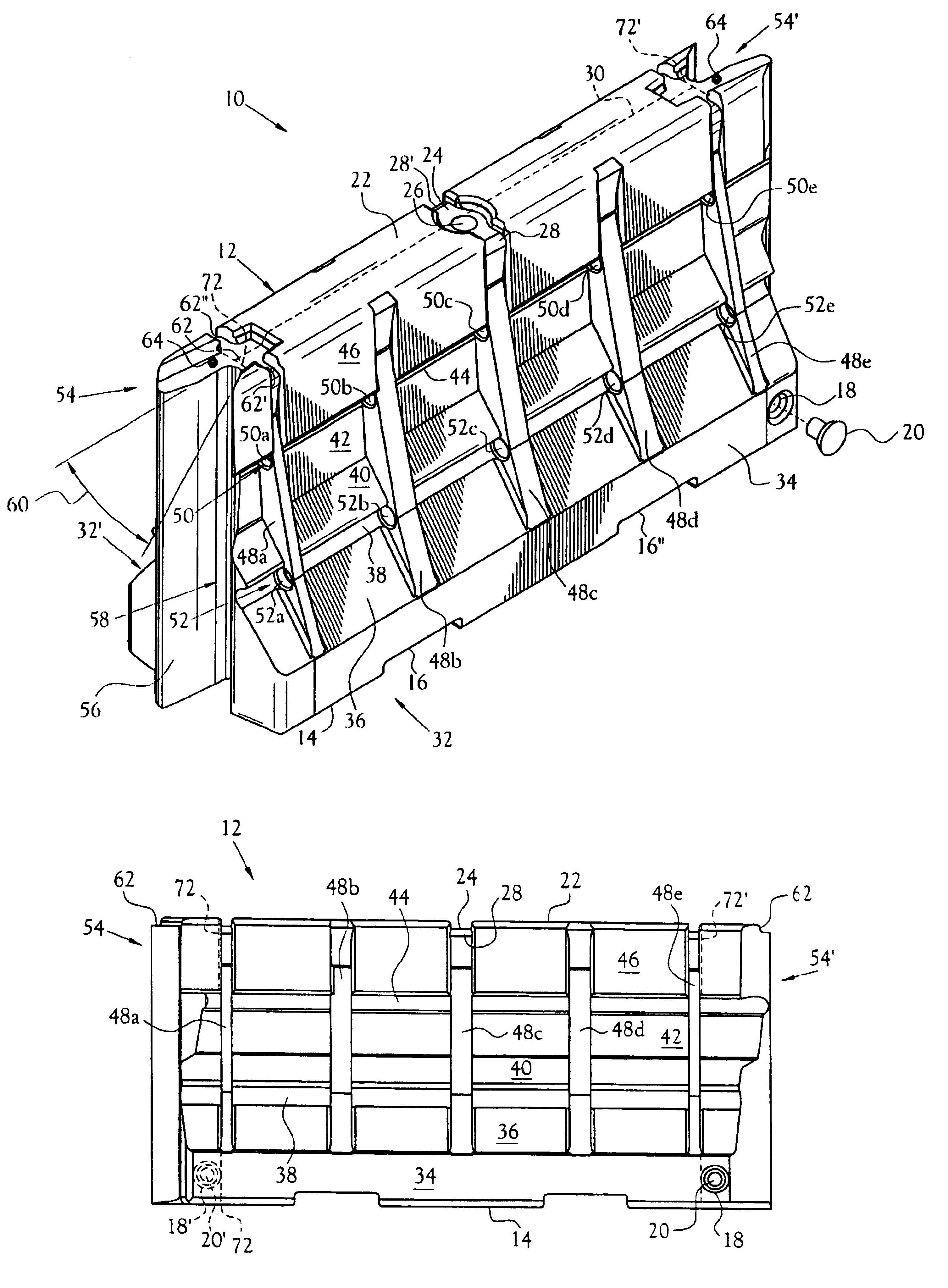
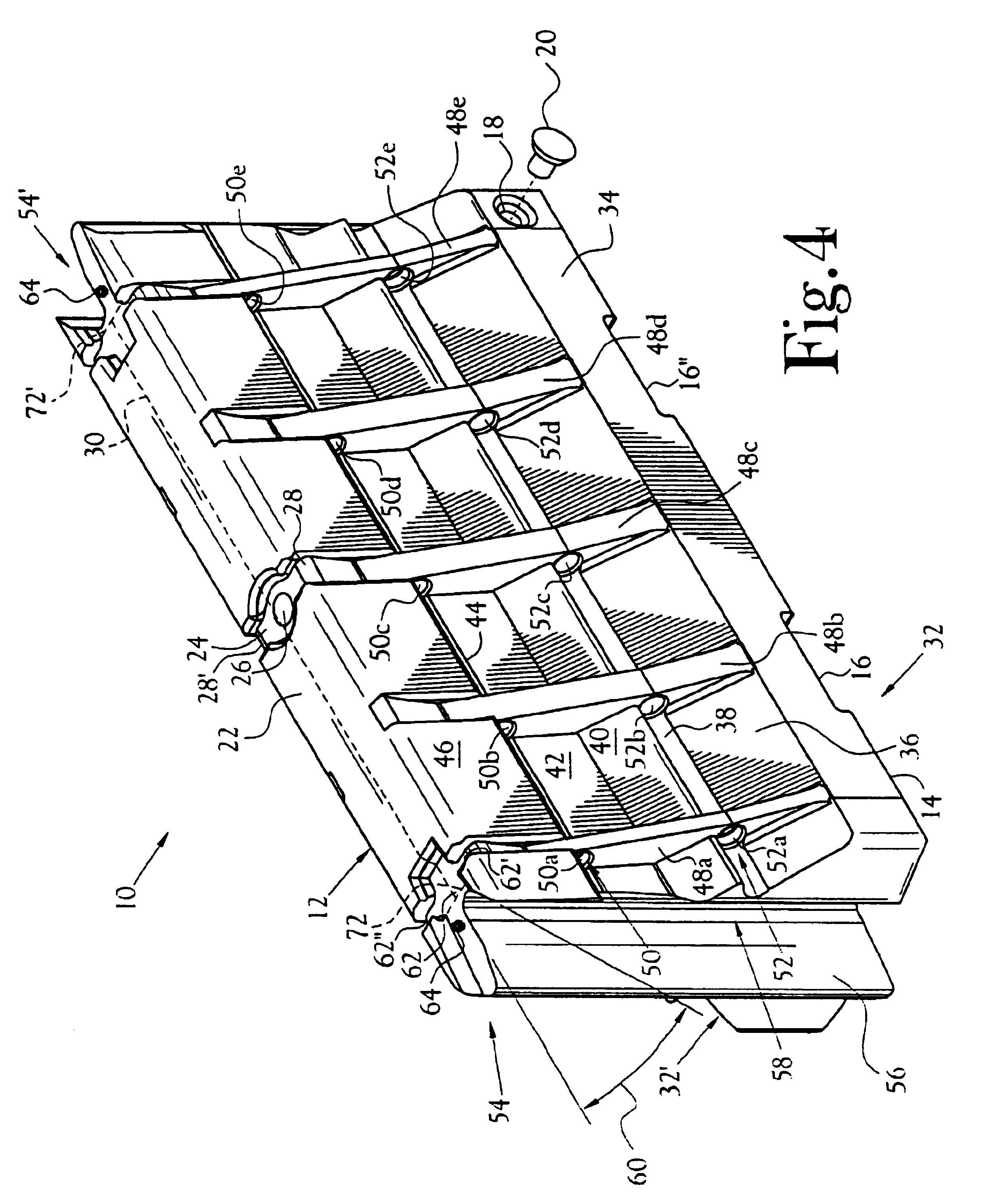
A protection barrier system 10 is disclosed having a plurality of configurations to provide multiple levels of protection during use for channeling vehicular traffic, providing impact energy-absorption as roadway barriers, controlling crowds, delineating parking areas, and providing security around buildings. The protection barrier system 10 is illustrated in FIG. 4 and includes an elongated barrier 12 having a hollow interior 12′ enclosed by a base 14, a top surface 22, a first side wall 32, a second side wall 32′, a first end 54 and a like-configured second end 54′. The elongated barrier 12 is connectable end-to-end by nesting of either end 54, 54′ with additional like-configured ends of similar configured protection barriers to form a plurality of barriers aligned in straight or curved orientations. The length of each barrier 12 can be increased during a production process to provide alternative lengths (see FIGS. 12 and 13) depending on the use. During assembly of a plurality of...


PUM


Abstract

A protection barrier system for energy-absorption of impacts includes an elongated barrier defining a chamber therein. The barrier includes side walls having a plurality of connected non-vertical wall segments and a plurality of buttresses positioned vertically at spaced apart locations along each side wall. One or more guide channels are positioned on each side wall in horizontal alignment with similar guide channels on like-configured barriers. A coupling is disposed on each opposed end of the barrier for coupling of either barrier end juxtaposed in end-to-end nested arrangement with like barriers. A supplemental energy-absorbing system is connectable between opposed ends of end-to-end coupled barriers, providing energy-absorbing tubes removably inserted through each guide channel of each barrier. Cables are extendable through the tubes in the guide channels of the nested barriers, providing additional energy-absorption and deterrence from breaching of the barriers. A method of manufacture for the protection barrier is also disclosed.

Description

BACKGROUND OF THE INVENTION1. Field of InventionThis invention pertains to temporary barriers utilized for channeling of vehicles and protection of workers along roads. More particularly, this invention pertains to movable energy-absorbing barriers having a plurality of configurations providing multiple levels of collision protection.2. Description of the Related ArtSafety barriers are utilized along roadways and near building construction sites to channel vehicles past construction areas in order to minimize vehicle intrusion into worker occupied areas for protection of workers from vehicle impacts. Prior safety barriers typically include portable containers composed of semi-rigid plastic material formed into various shapes that are generally light-weight for transport between work sites, but can be filled with sand or water during use as a stationary barrier. Prior elongated safety barriers include end portions that are generally planar to allow end-to-end positioning of rectangul...

Claims


Application Information

Patent Timeline
Patent Type & Authority Patents(United States)
IPC IPC(8): E01F15/08E01F15/00E01F15/02E01F15/14
CPCE01F15/088E01F15/086
Inventor DAVIS, C. REEDMCCOLL, RICHARD G.
Owner SAFETY BARRIERS
Why Eureka
Try Eureka