Two piece heat sink and device package

a heat sink and device technology, applied in the direction of electrical apparatus construction details, electrical apparatus casings/cabinets/drawers, support structure mounting, etc., can solve the problems of reducing the overall efficiency and affecting the operation of the heat sink

Inactive Publication Date: 2005-03-08
FCA US
View PDF13 Cites 99 Cited by
  • Summary
  • Abstract
  • Description
  • Claims
  • Application Information

AI Technical Summary

Benefits of technology

Still other objects of the invention are satisfied by a two piece electronic component heat sink and device package comprising a first piece configured to retain electronic components, and a second piece having a hinge region configured to pivotably connect the second piece to the first piece, and a snap lock region configured to secure the second piece to the first piece.
These and other objects of the invention are satisfied by a two piece electronic component heat sink and device package for an electronic circuit board comprising: a first piece having an index slot for retaining said circuit board; and a second piece having a hinge region configured to pivotably connect the second piece and the first piece, and a snap lock region configured to secure the second piece to the first piece.

Problems solved by technology

Since the vacuum tube, heat has been the anathema of electronic components.
Such configuration involves a blind assembly procedure and since visual inspection is impossible, must frequently be repaired by replacing both the circuit board and the heat sink assembly.
In many vehicles, the electronic components are located in the engine compartment where increased ambient temperature reduces the overall efficiency of the heat sink.
In addition, vehicle electronics confront a severe environment where dirt and vibration levels constantly challenge the integrity of the processors as well as their connections to related devices.

Method used


Image

  • Two piece heat sink and device package
  • Two piece heat sink and device package
  • Two piece heat sink and device package

Examples


Embodiment Construction

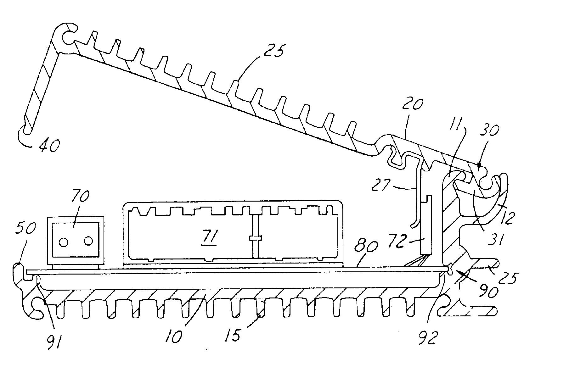
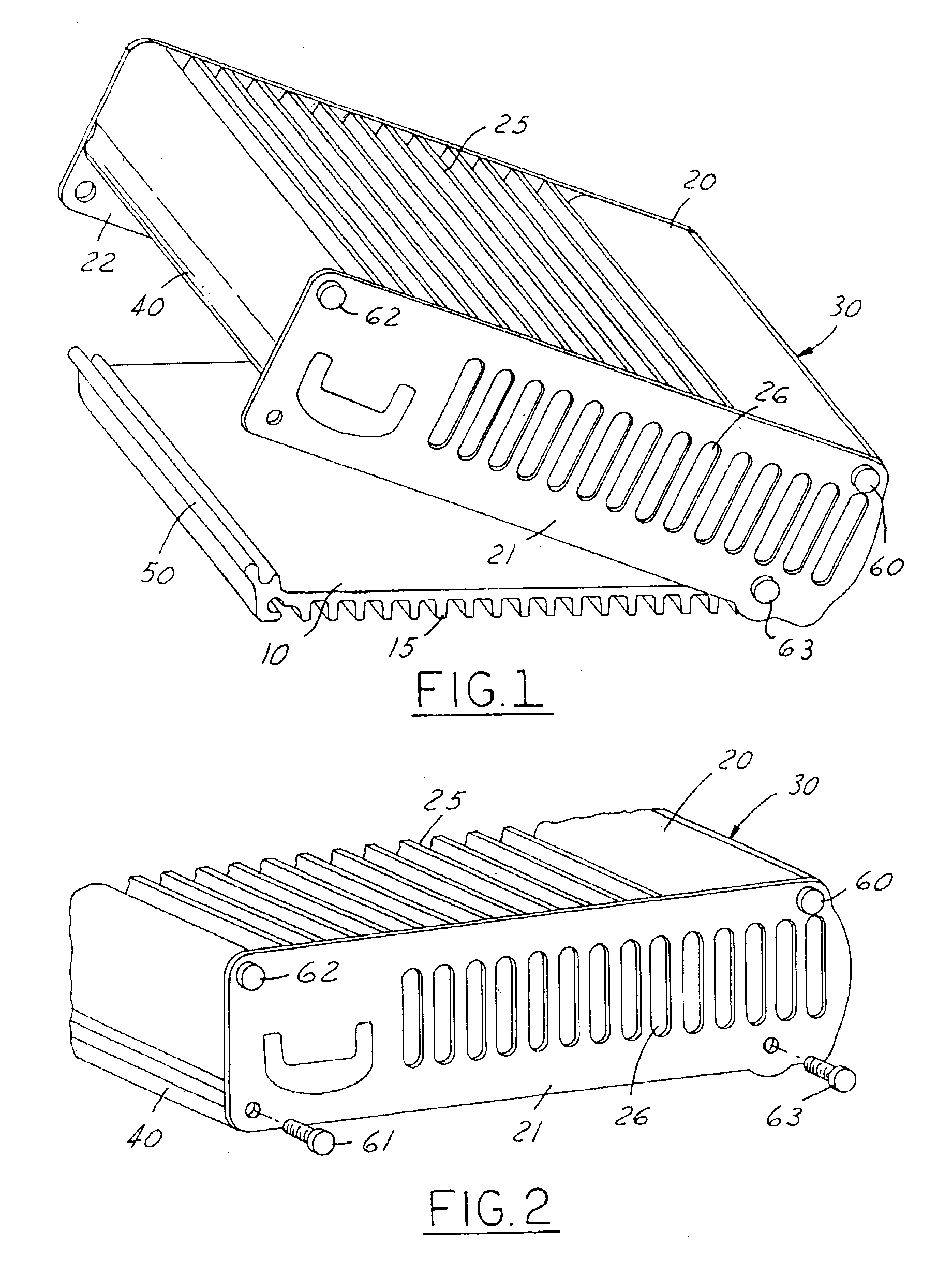
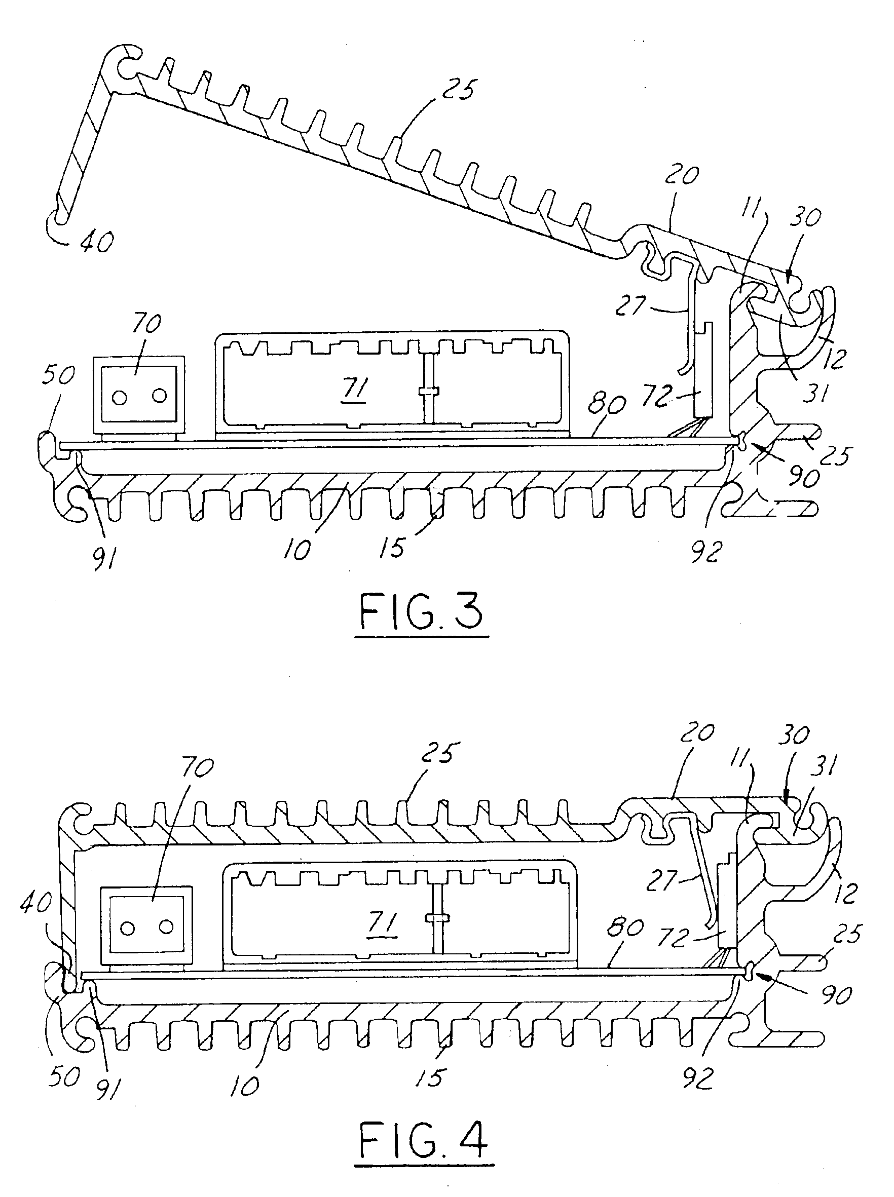
A two piece electronic component heat sink and device package of the present invention comprises a first piece configured to retain electronic components to be packaged; and a second piece having a hinge region configured to moveably connect the second piece to the first piece, and a snap lock region configured to removeably secure the second piece to the first piece.

Electronic component as used herein refers to a circuit board, an integrated circuit, an encapsulated processing chip, etc. or combination thereof configured to operate in conjunction with each other to function as an amplifier, power supply, computer, etc.

The first piece is specifically configured to retain an electronic component or components. This can be accomplished, for example, via a molded in receptacle or the like corresponding in size and shape to the electronic component. This receptacle can be as simple as a groove or projecting pins, or as elaborate as a locking connector. Alternatively, the first piece may...


PUM


Abstract

A two piece electronic component heat sink and device package comprising a first piece configured to retain electronic components, and a second piece having a hinge region configured to moveably connect the second piece to the first piece, and a snap lock region opposite the hinge region, the snap lock region configured to secure the second piece to the first piece. A two piece electronic component heat sink and device package for a circuit board comprising: a first piece having an index slot for retaining said circuit board, and a second piece having a hinge region configured to pivotably connect the second piece and the first piece, and a snap lock region configured to secure the second piece to the first piece.

Description

FIELD OF THE INVENTIONThis invention relates to a combination heat sink package for circuit boards and other electronic components. More particularly, this invention relates to a heat sink package for mounting electronic components in vehicle applications.BACKGROUND OF THE INVENTIONSince the vacuum tube, heat has been the anathema of electronic components. Advances in components and design have addressed this to some extent. Modern circuits do more using less power. Many subcomponents of modern electronics are barely warm after hours of use. But modern integrated circuits pack so much into such a small area that heat sinks, particularly for the central processor chip are commonplace. Such heat sinks may be passive or active. For example, passive finned heat sinks are described in U.S. Pat. No. 6,518,660 B2 and U.S. Published Application No. US 2001 / 0030037 A1; active heat sinks that integrate fans or liquid cooling are described in U.S. Pat. Nos. 6,459,576 and 6,519,148, respectivel...

Claims


Application Information

Patent Timeline
Patent Type & Authority Patents(United States)
IPC IPC(8): H01L23/40H01L23/34H05K7/20
CPCH01L23/4093H05K7/20409H01L2924/0002H01L2924/00
Inventor ROBERTSON, MICHAEL FBROWN, GARY L
Owner FCA US
Why Eureka
Try Eureka