Air flow system and method for facilitating cooling of stacked electronics components

a technology of electronics components and air flow, which is applied in the direction of electrical equipment, electrical apparatus, electrical apparatus contruction details, etc., can solve the problems of unmanageable frame level approach, cooling challenge, and recirculation problems, and achieve the effect of facilitating cooling of rack-mounted electronic equipmen

Inactive Publication Date: 2005-10-27
IBM CORP
View PDF12 Cites 260 Cited by
  • Summary
  • Abstract
  • Description
  • Claims
  • Application Information

AI Technical Summary

Benefits of technology

[0011] The shortcomings of the prior art are overcome and additional advantages are provided through an air flow system for facilitating cooling of rack-mounted electronic equipment. The air flow system includes an inlet duct configured to attach to the rack-mounted electronic equipment to at least partially cover an air-intake side thereof, and define a supply air flow plenum for directing air from a conditioned air source into the air-intake side of the rack-mounted electronic equipment. The inlet duct has a primary, conditioned air inlet at a first end for receiving conditioned air from the conditioned air source, and is tapered from the first end to a second end thereof, with the supply air flow plenum having a varying air flow cross-section, and wherein the inlet duct further includes an auxiliary room air inlet for providing supplemental air to the supply air flow plenum, wherein the auxiliary room air inlet is disposed closer to the first end of the inlet duct than the second end thereof, thereby facilitating mixing of the conditioned air with the room air within the supply air flow plenum prior to delivery thereof to the air-intake side of the rack-mounted electronic equipment.
[0012] In another aspect, a combined air flow system and rack-mounted electronic equipment apparatus is provided, which includes a rack unit having a plurality of drawer units each containing an electronic unit. The rack unit is at least partially air cooled and has an air-intake side and an air-outlet side. An inlet duct is attached to the rack unit to at least partially cover the air-intake side thereof, and define a supply air flow plenum for directing air from a conditioned air source into the air-intake side of the rack unit. The inlet duct has a primary, conditioned air inlet at a first end for receiving conditioned air from the conditioned air source, and is tapered from the first end to a second end thereof, with the supply air flow plenum having a varying air flow cross-section. The inlet duct further includes an auxiliary room air inlet for providing supplemental room air to the air-intake side of the rack unit. The auxiliary room air inlet is disposed closer to the first end of the inlet duct than the second end thereof, thereby facilitating mixing of conditioned air with room air within the supply air flow plenum prior to delivery thereof to the air-intake side of the rack unit.
[0013] In a further aspect, a method for facilitating cooling of rack-mounted electronic equipment is provided. The method includes providing a duct configured to attach to rack-mounted electronic equipment to at least partially cover an air-intake side thereof, and define a supply air flow plenum having a varying air flow cross-section for directing air from a conditioned air source into the air-intake side of the rack-mounted electronic equipment. The providing further includes providing a first opening at a first end of the duct for facilitating conditioned air flow from a conditioned air source into the supply air flow plenum for supply to the air-intake side of the rack-mounted electronic equipment, and providing an adjustable second opening in the duct for facilitating supplemental room air flow into the supply air flow plenum for supply to the air-intake side of the rack-mounted electronic equipment. The adjustable second opening is disposed closer to the first end of the duct than a second end of the duct, thereby facilitating mixing of the conditioned air flow with the supplemental air flow within the supply air flow plenum prior to delivery thereof to the air-intake side of the rack-mounted electronic equipment.

Problems solved by technology

This trend poses a cooling challenge at both the module and system level.
However, this approach is becoming unmanageable at the frame level in the context of a computer installation (e.g., data center).
In such installations not only will the room air conditioning be challenged, but the situation may also result in recirculation problems with some fraction of the “hot” air exiting one frame being drawn into the air inlets of the same frame or a nearby frame.
This increase in cooling air temperature may result in components exceeding their allowable operating temperature or a reduction in long term reliability of the components.
A drawback of the solution is that it requires that water be available in the data center, which is not always the case.
Finally, there is always the concern of the consequences of a water leak.

Method used


Image

  • Air flow system and method for facilitating cooling of stacked electronics components
  • Air flow system and method for facilitating cooling of stacked electronics components
  • Air flow system and method for facilitating cooling of stacked electronics components

Examples


Embodiment Construction

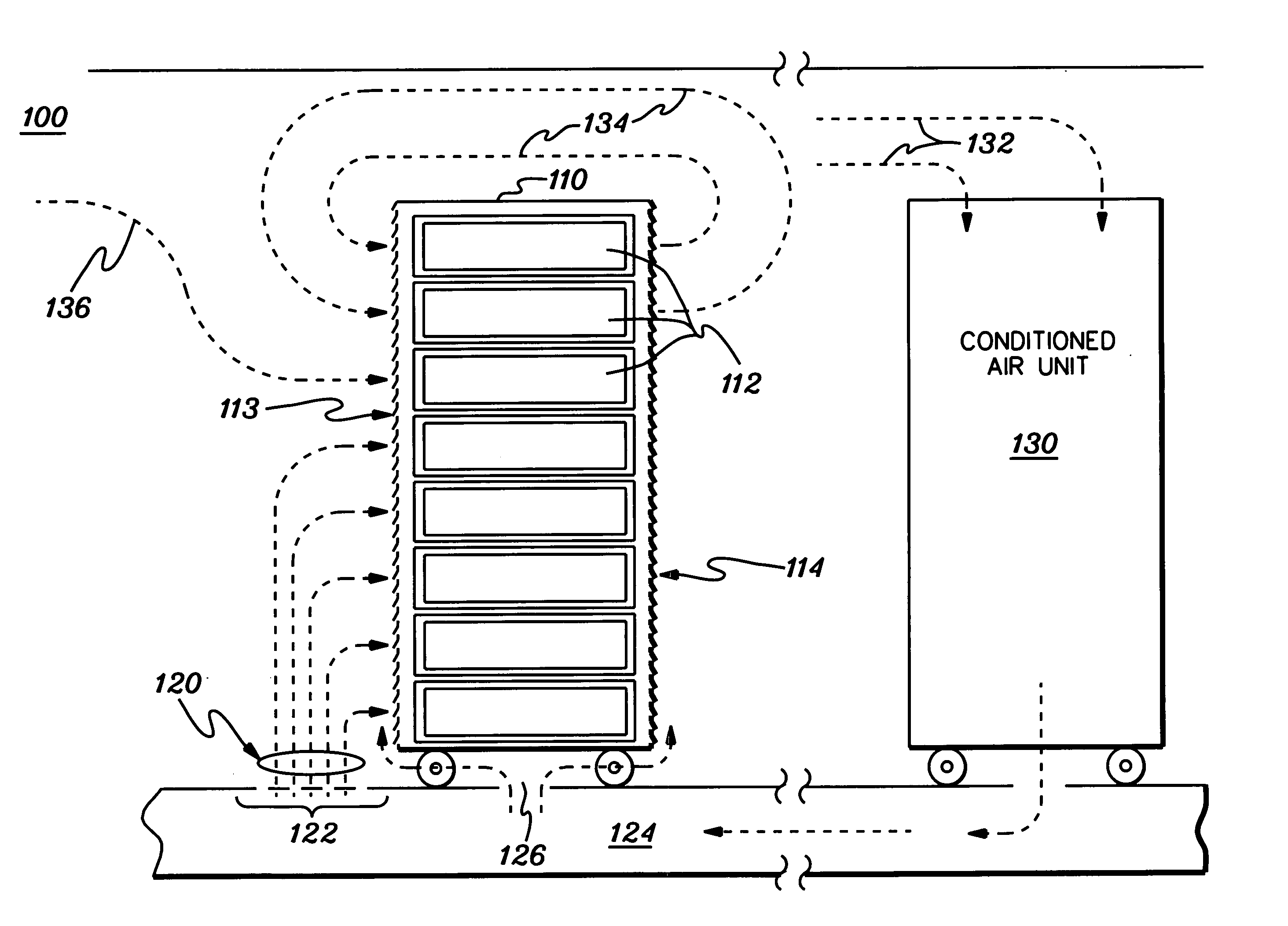
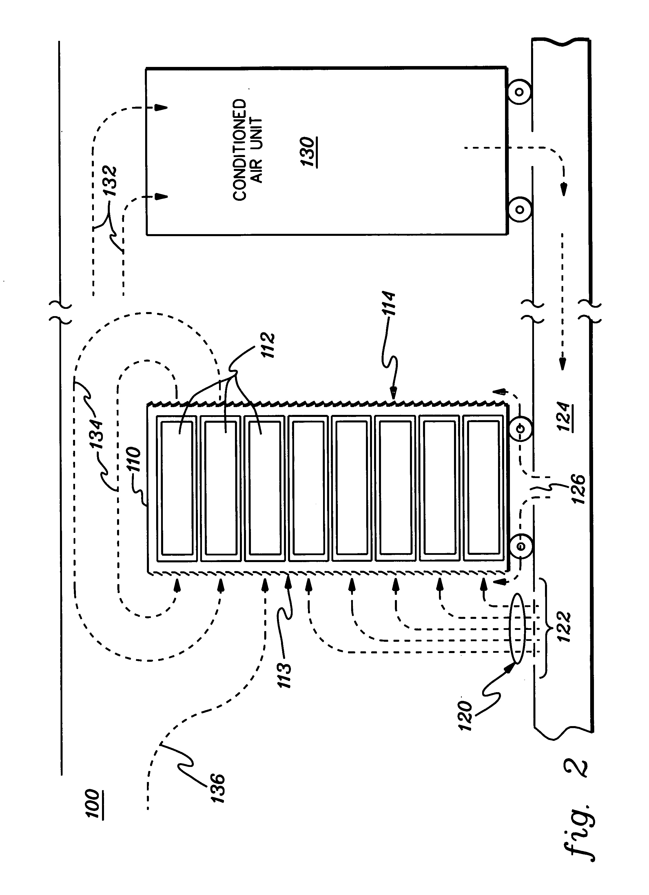
[0027] As used herein, the terms “electronics rack”, “rack-mounted electronic equipment” and “rack unit” are used interchangeably, and include any housing, frame, rack, compartment, etc., having a heat generating component of a computer system or electronics system. In one embodiment, an electronics rack may comprise multiple electronics drawers each having one or more heat generating components disposed therein requiring cooling.

[0028] Reference is now made to the drawings, which are not drawn to scale for ease of understanding, wherein the same reference numbers used throughout different figures designate the same or similar components.

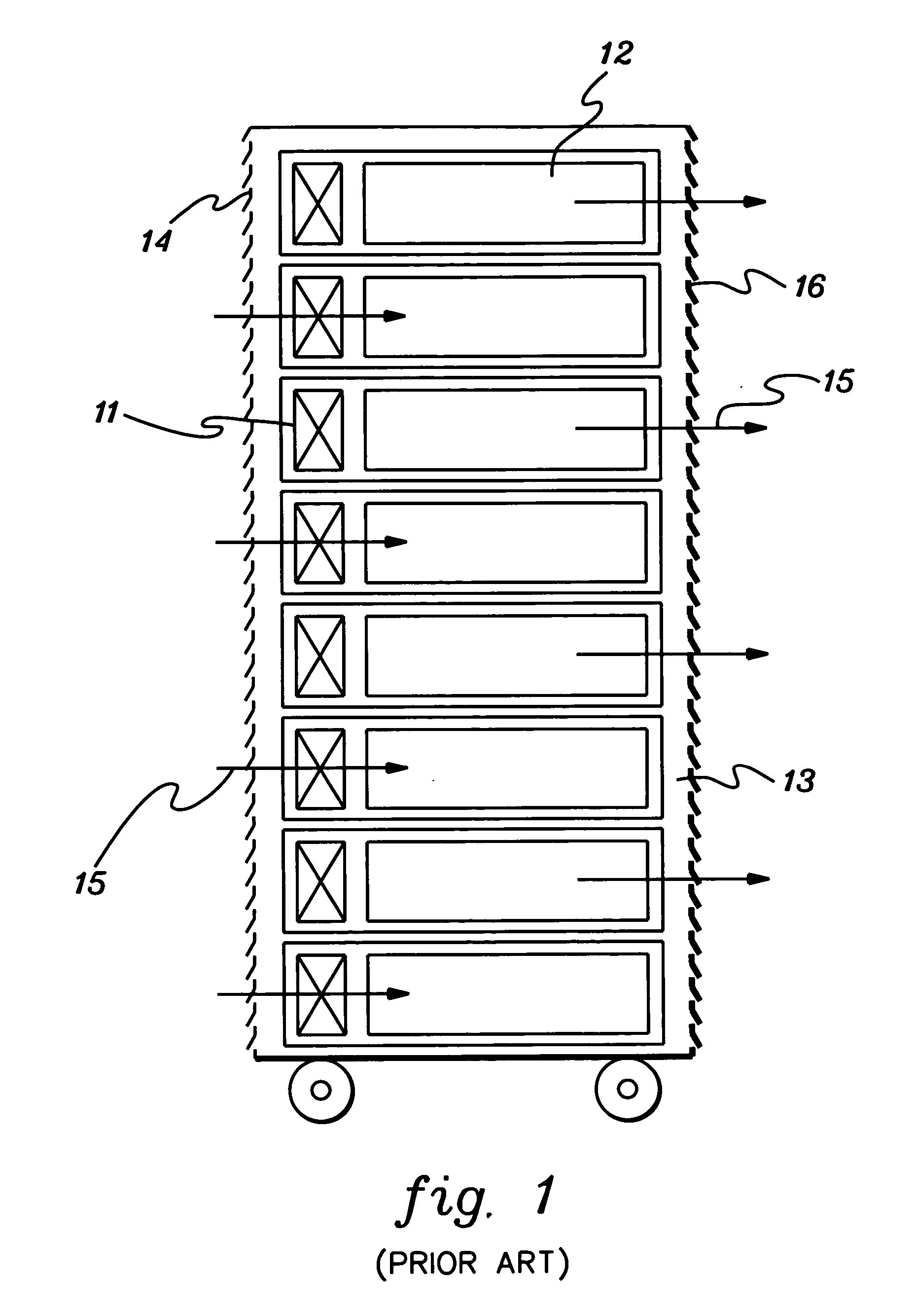
[0029] As shown in FIG. 1, in rack-mounted configurations typical in the prior art, a plurality of air moving devices (e.g., fans or blowers 11) provide forced air flow 15 needed to cool the electronic components 12 within the drawers 13. Cool air is taken in through the louvered covers 14 in the front (i.e., air-intake side) of the frame and exha...


PUM


Abstract

An air flow system and method are provided which include a duct configured to mount either as an inlet or outlet duct to an electronics rack. When mounted to cover an air-intake side of the electronics rack, a supply air flow plenum is defined for directing conditioned air to the air-intake side. The duct includes a first air inlet at a first end for receiving the conditioned air, and is tapered from the first end to a second end thereof, with the supply plenum having a varying air flow cross-section. The duct further includes a second air inlet for providing supplemental room air to the plenum. The second inlet is disposed adjacent to the first inlet, thereby facilitating mixing of conditioned air with room air within the supply air flow plenum prior to delivery thereof to the air-intake side of the electronics rack.

Description

CROSS-REFERENCE TO RELATED APPLICATIONS [0001] This application contains subject matter which is related to the subject matter of the following applications, each of which is assigned to the same assignee as this application and each of which is hereby incorporated herein by reference in its entirety: [0002]“Method and Apparatus For Combined Air and Liquid Cooling Of Stacked Electronics Components”, Chu et al., Ser. No. 10 / 303,284, filed Nov. 25, 2002; [0003]“Method and System For Cooling Electronics Racks Using Pre-Cooled Air”, Chu et al., Ser. No. 10 / 612,355, filed Jul. 2, 2003; and [0004]“Condensate Removal System and Method For Facilitating Cooling Of An Electronics System”, Chu et al., Ser. No. ______, filed Mar. 30, 2004 (Attorney Docket Number POU920040003US1).TECHNICAL FIELD [0005] The present invention relates in general to systems and methods for facilitating cooling of rack-mounted assemblages of individual electronics units, such as rack-mounted computer server units. BA...

Claims


Application Information

Patent Timeline
Patent Type & Authority Applications(United States)
IPC IPC(8): H05K7/20
CPCH05K7/20745H05K7/20736
Inventor CHU, RICHARD C.ELLSWORTH, MICHAEL J. JR.SCHMIDT, ROGER R.SIMONS, ROBERT E.
Owner IBM CORP
Why Eureka
Try Eureka