Encapsulated solenoid assembly having an integral armor tube cable protector

a technology of armor tube and solenoid, which is applied in the direction of magnets, operating means/release devices of valves, magnetic bodies, etc., can solve the problems of increasing the cost associated with manufacturing and assembling the solenoid, affecting the performance of the solenoid, and affecting the operation of the solenoid

Inactive Publication Date: 2005-03-08
KURZ KASCH
View PDF18 Cites 7 Cited by
  • Summary
  • Abstract
  • Description
  • Claims
  • Application Information

AI Technical Summary

Benefits of technology

It is one object of the present invention to provide an improved encapsulated solenoid assembly. It is another object of the present invention to provide an improved method for manufacturing an encapsulated solenoid assembly.

Problems solved by technology

In such applications, the solenoid may by exposed to relatively harsh environments, including exposure to moisture, contaminants or corrosive substances that may adversely affect operation of the solenoid and / or lead to premature failure of the solenoid.
However, such routing tends to compromise fluid or contamination resistance.
Regardless of which of the above techniques is used, attachment of an external sheath or cable housing to the solenoid body involves the use of a complex attachment arrangement and / or multiple fastener components, is typically time consuming, and may require precise alignment with preformed openings, all of which tend to increase the costs associated with manufacturing and assembling the solenoid.
Maintaining an adequate seal between the electrical leads and the solenoid body may also present difficulties.

Method used


Image

  • Encapsulated solenoid assembly having an integral armor tube cable protector
  • Encapsulated solenoid assembly having an integral armor tube cable protector
  • Encapsulated solenoid assembly having an integral armor tube cable protector

Examples


Embodiment Construction

For the purposes of promoting an understanding of the principles of the invention, reference will now be made to the embodiments illustrated in the drawings and specific language will be used to describe the same. It will nevertheless be understood that no limitation of the scope of the invention is hereby intended, such alterations and further modifications in the illustrated devices, and such further applications of the principles of the invention as illustrated herein being contemplated as would normally occur to one skilled in the art to which the invention relates.

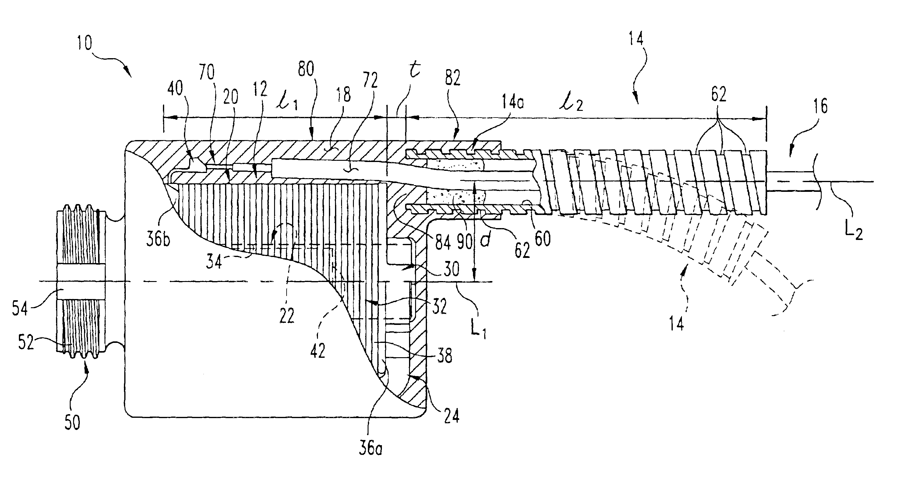
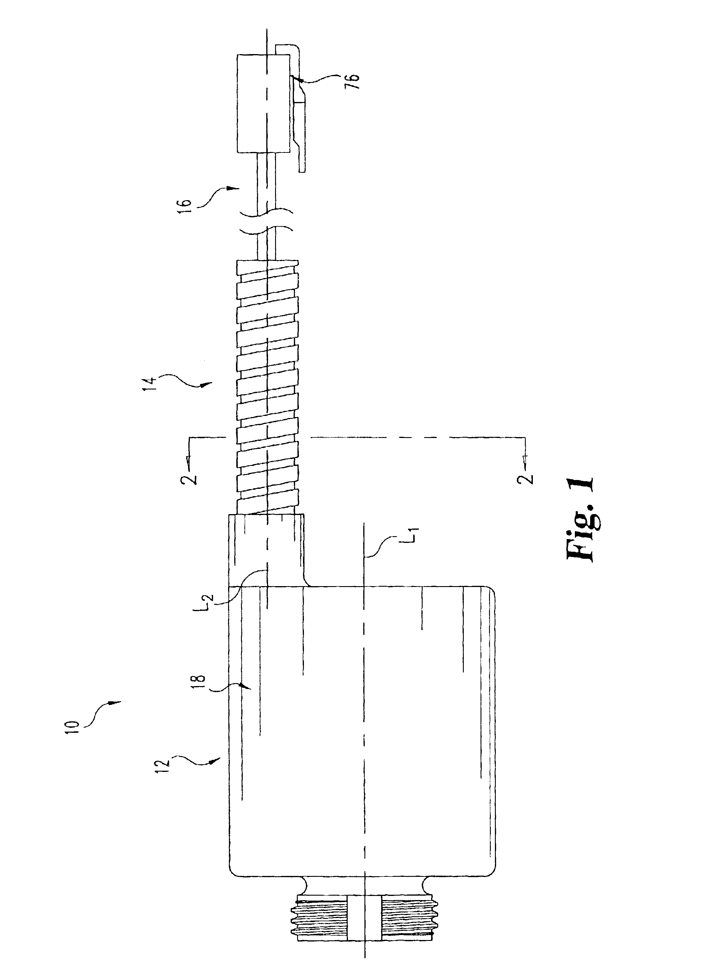
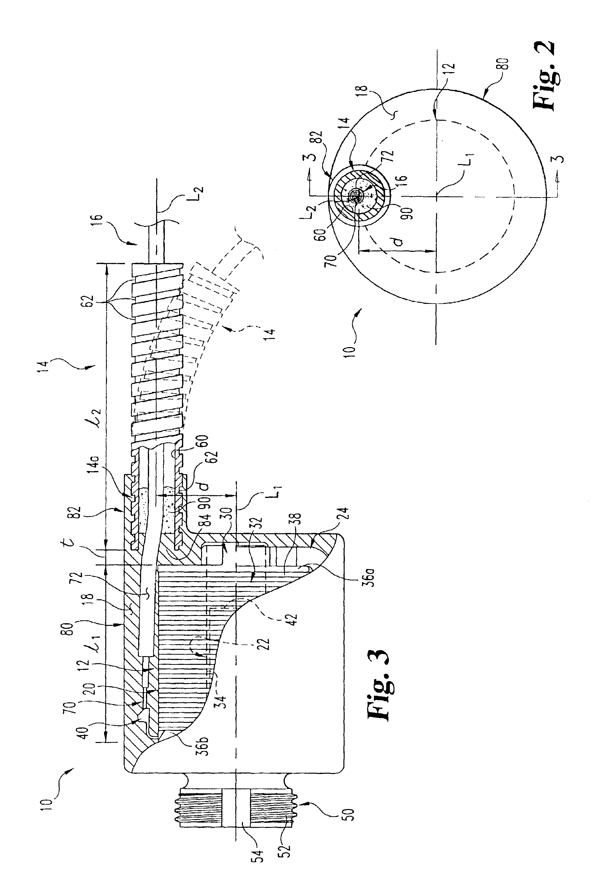
Referring to FIG. 1, shown therein is a solenoid assembly 10 according to one form of the present invention. The solenoid assembly 10 is generally comprised of an electronic actuator 12, an elongate tube member 14, and an electrical conductor 16 extending through the elongate tube member 14 and electrically connected to the electronic actuator 12. An encapsulation material 18 surrounds the electronic actuator 12 and a...


PUM

PropertyMeasurementUnit
electricalaaaaaaaaaa
lengthaaaaaaaaaa
metallicaaaaaaaaaa

Abstract

An encapsulated solenoid assembly including an electronic actuator and an elongate metallic armor tube for receiving an electrical conductor therethrough which is electrically connected to the electronic actuator. The electronic actuator and an end portion of the armor tube are encapsulated within an outer casing of encapsulation material to integrally couple the armor tube with the electronic actuator without the use of additional connection components or complex attachment arrangements. In one embodiment, the armor tube is corrugated to facilitate bending and to aid in maintaining engagement with the encapsulation material. In another embodiment, the electronic actuator includes a magnetic plunger that is displaceable along an actuation axis, with the armor tube extending along a longitudinal axis laterally offset from the actuation axis. In a further embodiment, the electrical conductor extends alongside a substantial length of the electronic actuator so as to become embedded within the outer shell of encapsulation material.

Description

FIELD OF THE INVENTIONThe present invention relates generally to the field of solenoids, and more particularly relates to an encapsulated solenoid assembly having an integral armor tube cable protector.BACKGROUND OF THE INVENTIONSolenoid devices are used in a wide variety of automotive and industrial applications to control the flow of a gas or fluid. In such applications, the solenoid may by exposed to relatively harsh environments, including exposure to moisture, contaminants or corrosive substances that may adversely affect operation of the solenoid and / or lead to premature failure of the solenoid. As a result, solenoid devices are sometimes encapsulated in an outer layer of protective material to provide a barrier between the internal working components of the solenoid device and the external environment.Encapsulated solenoids are typically designed such that the electrical leads that provide power and / or control signals to the solenoid extend laterally through the outer shell o...

Claims


Application Information

Patent Timeline
Patent Type & Authority Patents(United States)
IPC IPC(8): H01F7/128H01F7/08H01F7/06H01F27/04H01F27/02
CPCH01F7/128H01F7/06H01F27/022H01F27/04H01F2007/062
Inventor CALLIS, BRADVANNETTE, DANO
Owner KURZ KASCH
Why Eureka
Try Eureka