Head rest apparatus

a head rest and apparatus technology, applied in the direction of chairs, pedestrian/occupant safety arrangements, vehicular safety arrangements, etc., can solve the problems of difficult to provide with the head rest apparatus, difficulty in formation, etc., and achieve the effect of reliable operation

Inactive Publication Date: 2005-03-15
NHK SPRING CO LTD
View PDF17 Cites 101 Cited by
  • Summary
  • Abstract
  • Description
  • Claims
  • Application Information

AI Technical Summary

Benefits of technology

Accordingly, an object of the present invention is to provide a head rest apparatus which can ensure a reliable operation without a human body of a passenger being interfered with an urging member for urging a head rest frame in a backward tilting direction and can be provided even in the case that a size, a thickness or the like of a seat back is restricted.
In accordance with the present invention, the urging member always urging the head rest frame in the backward tilting direction is arranged so as to backward tilt the head rest from the rear portion. That is, the urging member is arranged at the back of the head rest frame, whereby it is possible to prevent the urging member from protruding forward and to an outer side in a width direction from the seat back frame. Accordingly, a reliable operation can be ensured without the human body of the passenger being interfered with the urging member, and even in the case that the size, the thickness or the like of the seat back is restricted, the head rest apparatus can be equipped.

Problems solved by technology

Further, since it is impossible to secure a sufficient distance (denoted by reference symbol L) from the coil spring 33 to the surface of the cushion 24, it is necessary to form a pad member such as an urethane foam or the like constituting the cushion 24 thin, however, this formation requires a difficulty.
Further, there is a requirement of reducing a thickness and a width of the seat back according to some sizes of the automobile and some layouts of the seat, and in this case, it is difficult to provide with the head rest apparatus 30 using the coil springs 33 mentioned above in the seat.

Method used


Image

  • Head rest apparatus
  • Head rest apparatus
  • Head rest apparatus

Examples


Embodiment Construction

A description will be given of an embodiment in accordance with the present invention with reference to the accompanying drawings.

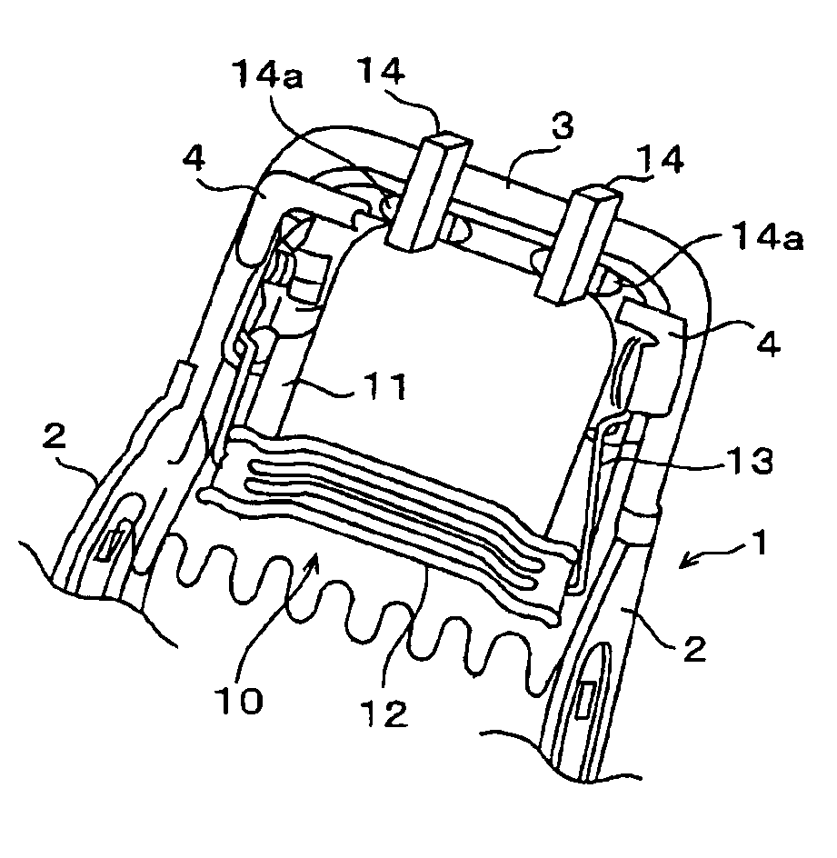
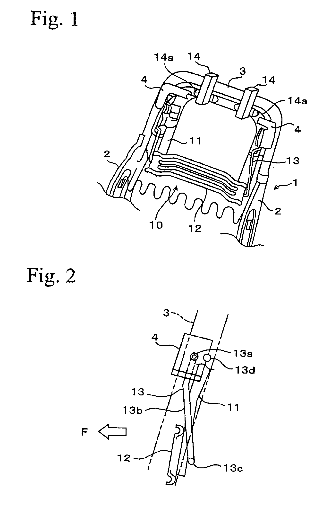
FIG. 1 shows a part of an inner structure of a seat back provided with a head rest apparatus 10 in accordance with an embodiment. In FIG. 1, reference numeral 1 denotes a seat back frame formed in a substantially reverse-U shape as seen from a front face. The seat back frame 1 is structured such that both ends of a C-shaped upper frame 3 are respectively fixed to upper ends of a pair of right and left side frames 2, and is mounted to a seat cushion via a reclining apparatus (not shown) provided between lower ends of the respective side frames 2 so as to freely tilt. The head rest apparatus 10 is provided in upper end portions of right and left portions extending in a vertical direction of the upper frame 3 via brackets 4.

The head rest apparatus 10 is mainly constituted by a C-shaped head rest frame 11 mounted to the respective brackets 4 via tilting shaft...


PUM


Abstract

The invention provides a head rest apparatus provided with a head rest frame supported to a seat back frame of a seat back via a tilting shaft so as to freely tilt and having an upper side of the tilting shaft to which a head rest is attached, a pressure receiving member provided in a lower side of the tilting shaft in the head rest frame and receiving a load applied from a front surface of the seat back to a backward portion, and an urging member engaging with the seat back frame and the head rest frame and always urging the head rest frame in a backward tilting direction, in which the head rest frame forward tilts around the tilting shaft corresponding to a supporting point and the head rest forward moving when the pressure receiving member is exposed to the load. The urging member is structured such as to urge the head rest frame in the backward tilting direction from a rear portion.

Description

BACKGROUND OF THE INVENTION1. Field of the InventionThe present invention relates to a head rest apparatus provided in a seat back in a seat for automobiles and reducing a whiplash syndrome applied to a passenger at a time of being collided from rear-end or the like.2. Background ArtFIG. 4 shows an inner structure of a reclining type seat back provided with a conventional head rest apparatus 30. In FIG. 4, reference numeral 21 denotes a seat back frame formed in a substantially reverse-U shape as seen from a front face. The seat back frame 21 is mounted to a seat cushion (not shown) via a reclining shaft 22 provided in a lower end so as to freely tilt. The head rest apparatus 30 is provided in upper end portions of right and left vertically extending portions of the seat back frame 21 via brackets 23.The apparatus 30 is mainly constituted by a C-shaped head rest frame 31 mounted to each of the brackets 23 via a tilting shaft so as to freely tilt in a longitudinal direction, a pressu...

Claims


Application Information

Patent Timeline
Patent Type & Authority Patents(United States)
IPC IPC(8): B60N2/48B60N2/42
CPCB60N2/4808B60N2/4885B60N2/4838B60N2/809B60N2/838B60N2/888
Inventor ITOH, KEISHIROU
Owner NHK SPRING CO LTD
Why Eureka
Try Eureka