Method for injection-molding an article having a hollow portion

a technology of injection molding and hollow parts, which is applied in the direction of dough shaping, manufacturing tools, food shaping, etc., can solve the problems of increased production cost, poor strength of the article, and complicated operation, and achieve accurate and easy control

Inactive Publication Date: 2005-03-15
MITSUBISHI ENG PLASTICS CORP
View PDF18 Cites 40 Cited by
  • Summary
  • Abstract
  • Description
  • Claims
  • Application Information

AI Technical Summary

Benefits of technology

It is therefore an object of the present invention to provide a method for injection-molding an article having a hollow portion, in which desired portions of the molded article made of two thermoplastic resins can be reliably constituted of the two thermoplastic resins and the thickness of each of the portions of the molded article made of the two thermoplastic resins can be accurately and easily controlled, and an injection-molding apparatus suiTable for carrying out the above injection molding method.
In the second or third injection-molding method of the present invention, the first or second molten thermoplastic resin is injected in a state where the cavity is separated (partitioned) into two spaces by the partition member, whereby the desired portions of the molded article can be reliably made of the first and second thermoplastic resins, and whereby the forms (for example, thickness, width and length) of the portions of the molded article which are made of the first and second thermoplastic resins can be accurately and easily controlled.

Problems solved by technology

The above method (1) requires an assembly step, and an article produced by the assembly generally has a problem in that the strength thereof is poor as compared with a molded article which is integrally formed.
In the above method (2), for producing (molding) the first member and the second member, it is required to carry out injection molding twice or it is required to prepare the first member beforehand, so that the operation is complicated and that an additional production cost is required.
In the above method (3), it is difficult to control the thickness of the portion covering the surface properties, and it is also difficult to constitute a desired portion of a molded article from a material (resin) having excellent surface properties.
In the paper feeding roller, however, the support shaft is desirably hard, and it is difficult to constitute a desired portion from a desired material in the production method disclosed in JP-A-10-281139.
Further, in the sandwich molding method, it is difficult to control the thickness of the soft material, and it is difficult to form the soft material on a surface of the resin material with positional accuracy and thickness accuracy.

Method used


Image

  • Method for injection-molding an article having a hollow portion
  • Method for injection-molding an article having a hollow portion
  • Method for injection-molding an article having a hollow portion

Examples


example 2

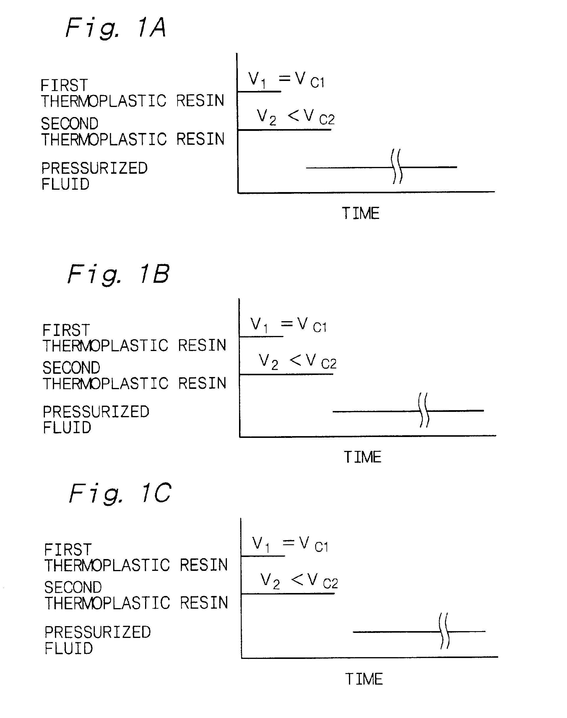
The injection-molding method of Example 2 is a variant of the injection-molding method of Example 1. In a step similar to [Step-120], the first thermoplastic resin was in a molten state when it came in contact with the second molten thermoplastic resin. In Example 2, the embodiment shown in FIG. 1B was employed as timings of the start and completion of an injection of the first molten thermoplastic resin and the second molten thermoplastic resin, and the start of an introduction of the pressurized fluid. Example 2 used the same injection-molding apparatus, the same first thermoplastic resin and the same second thermoplastic resin as those in Example 1.

[Step-200]

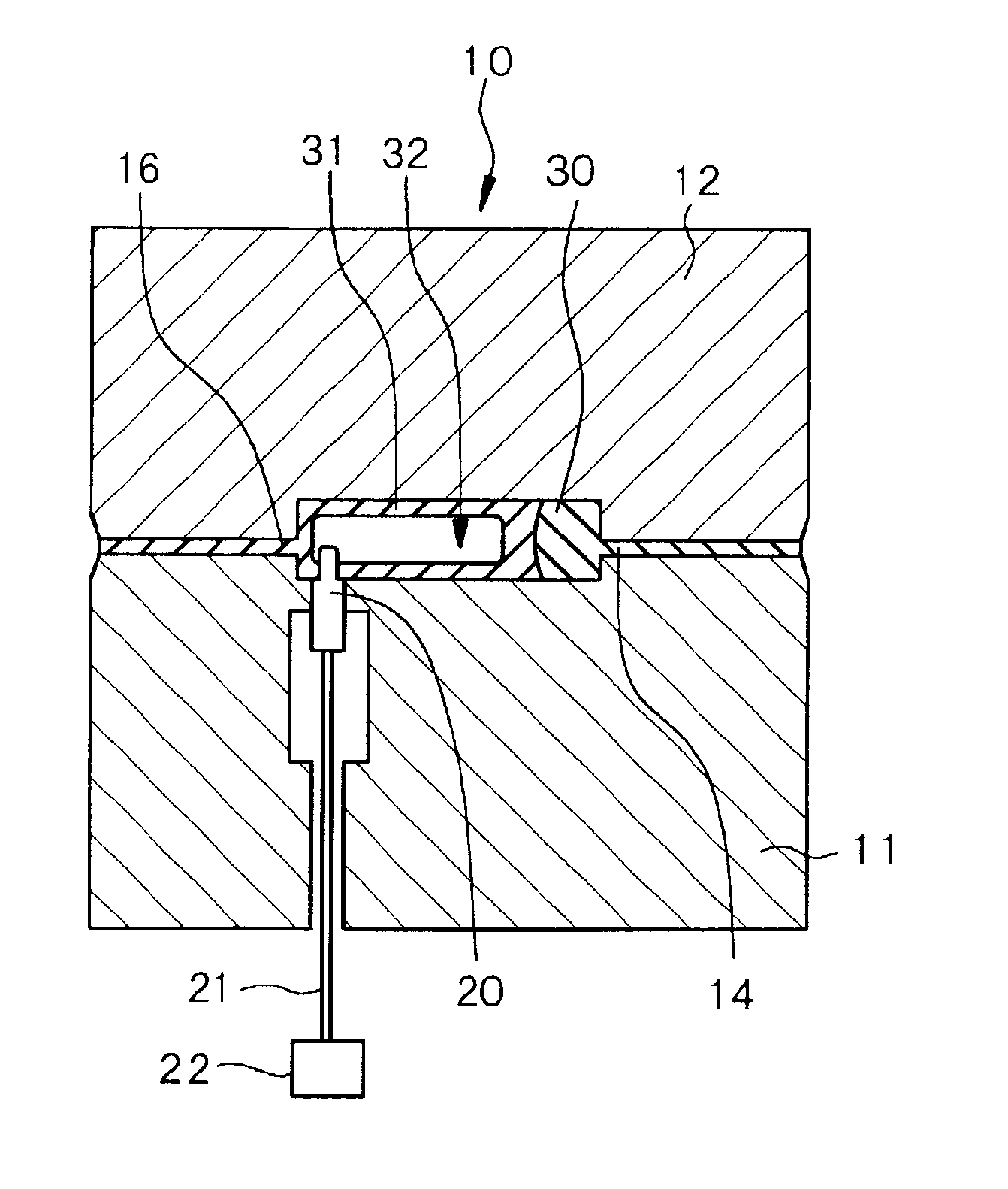
First, the first molten thermoplastic resin was injected into the cavity 13 from the first injection cylinder 15 through the first-molten-resin injection portion 14 in the same manner as in [Step-100] of Example 1. Concurrently with the start of injection of the first molten thermoplastic resin, the injection of the second mo...

example 3

Example 3 is concerned with the injection-molding apparatus having a partition member, provided by the present invention, and the second injection-molding method of the present invention. FIG. 19 shows a conceptual view of the injection-molding apparatus of Example 3. The injection-molding apparatus is the same as the injection-molding apparatus explained in Example 1 except that it has a movable partition member 40 and that the cavity 13 has a different form, so that a detailed explanation of the common features is omitted.

The partition member 40 is disposed in a portion of the cavity between a first cavity portion 13A that the first molten thermoplastic resin can occupy in the cavity 13 and a second cavity portion 13B that the second thermoplastic resin can occupy in the cavity 13. In Example 3, the partition member 40 is movable in directions in which it comes near to the second injection cylinder 17 and comes near to the first injection cylinder 15 by means of a hydraulic cylind...

example 4

Example 4 used an injection-molding apparatus that was the same as the injection-molding apparatus explained in Example 3 except that the surface of the partition member 40 which was to come in contact with the first molten thermoplastic resin was provided with a convexo-concave shape (undercut) as shown in FIG. 29A that is a schematic cross-sectional view obtained by cutting the partition member 40 with a plane at right angles with the longitudinal direction.

The injection-molding method of Example 4 is a variant of the injection-molding method of Example 3. The injection-molding method of Example 4 differs from that of Example 3 only in that a dwell time of 20 seconds under a pressure of 2.45×10⁷ Pa (250 kgf / cm2-G) was secured after completion of the injection of the first molten thermoplastic resin in a step similar to [Step-300]. By securing such a longer dwell time, the first thermoplastic resin in the first cavity portion 13A was cooled, and as a result, a portion of the first ...


PUM

PropertyMeasurementUnit
thicknessaaaaaaaaaa
temperatureaaaaaaaaaa

Abstract

An injection-molding apparatus comprises a mold assembly having a first-molten-resin injection portion for injecting a first molten thermoplastic resin into a cavity of the mold assembly, a second-molten-resin injection portion for injecting a second molten thermoplastic resin into the cavity, and a pressurized-fluid introducing portion for introducing a pressurized fluid into the second molten thermoplastic resin injected into the cavity. The injection-molding apparatus also comprises a first injection cylinder communicating with the first-molten-resin injection portion, and a second injection cylinder communicating with the second-molten-resin injection portion.

Description

BACKGROUND OF THE INVENTION1. Field of the InventionThe present invention relates to a method for injection-molding an article having a hollow portion, and more specifically, a method for injection-molding an article having a hollow portion according to a kind of two-color molding method, and an injection-molding apparatus suiTable for carrying out the above method.2. Description of Related ArtConventionally, an article having a hollow portion, in which the article is required not only to have surface properties such as an excellent appearance, slidability and chemical resistance but also to have rigidity, is produced by the following method. That is, (1) a method in which a first member for covering the surface properties (generally, an article having a solid portion) and a second member for covering the rigidity (generally, an article having a hollow portion) are separately injection-molded and then assembled, (2) a method in which a first member for covering the surface propertie...

Claims


Application Information

Patent Timeline
Patent Type & Authority Patents(United States)
IPC IPC(8): B29C45/16B29C45/17B29C45/26B29C45/00B29C45/13B29L9/00B29L22/00
CPCB29C45/1639B29C45/1705B29C45/1704
Inventor KAYANO, YOSHIHIROIMAIZUMI, HIROYUKIOCHIAI, KAZUAKI
Owner MITSUBISHI ENG PLASTICS CORP
Why Eureka
Try Eureka