

Method and apparatus for rack mounting computer components
a computer and component technology, applied in the direction of dismountable cabinets, electrical apparatus casings/cabinets/drawers, instruments, etc., can solve the problems of wasting space in the back plane and fan exhaust plenum, time-consuming replacement, and high cost of individual fans mounted in each componen
- Summary
- Abstract
- Description
- Claims
- Application Information
AI Technical Summary
Benefits of technology
Problems solved by technology
Method used
Image

Examples
Embodiment Construction
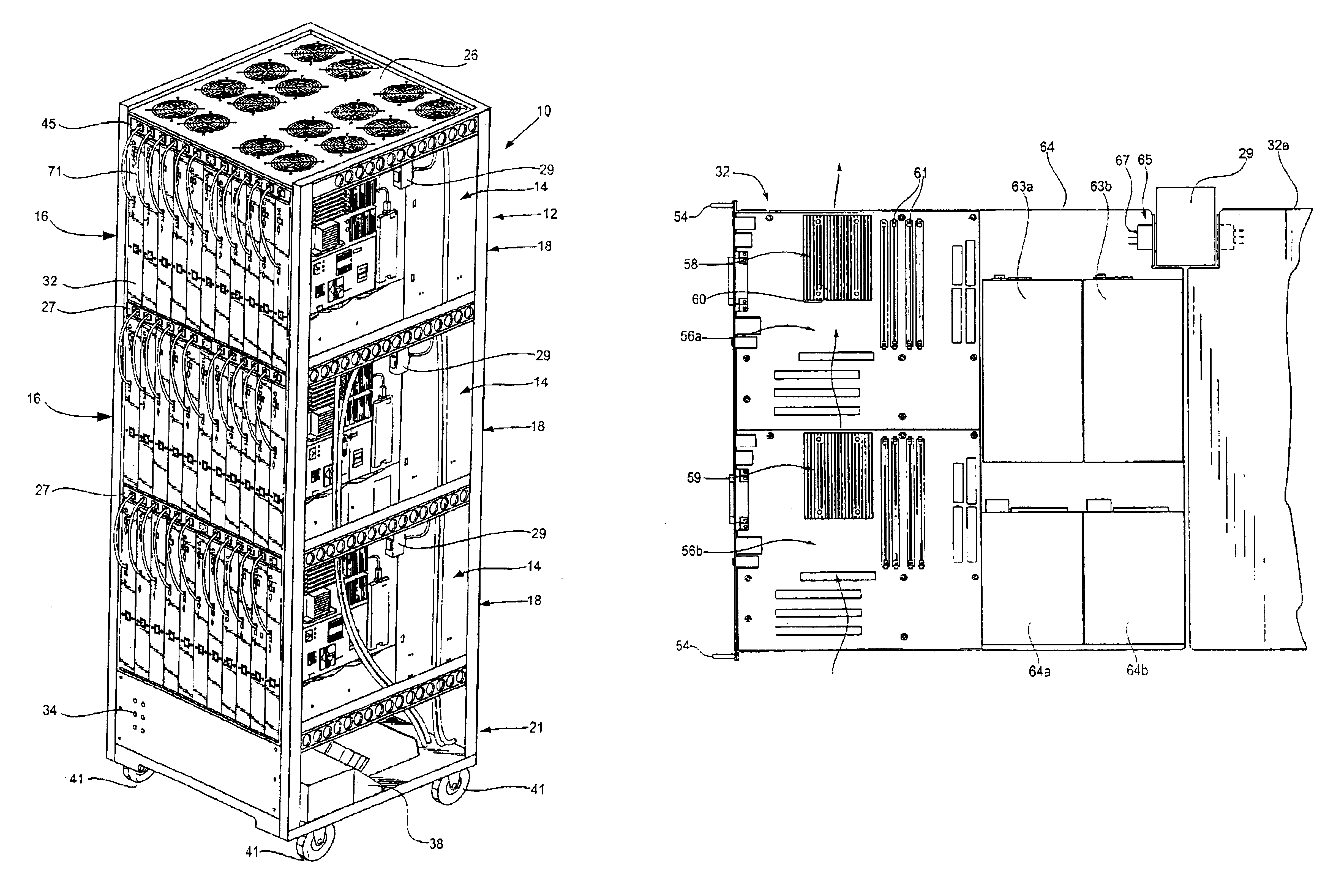
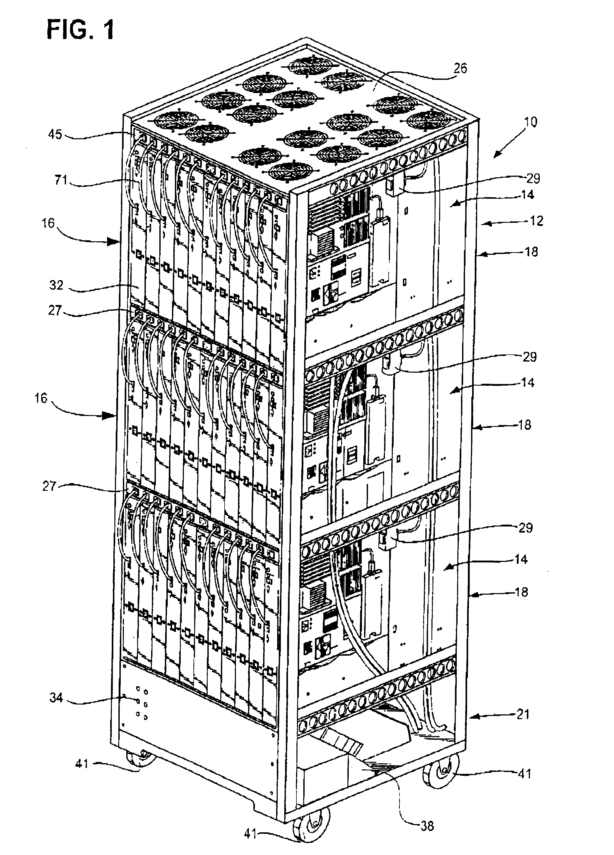
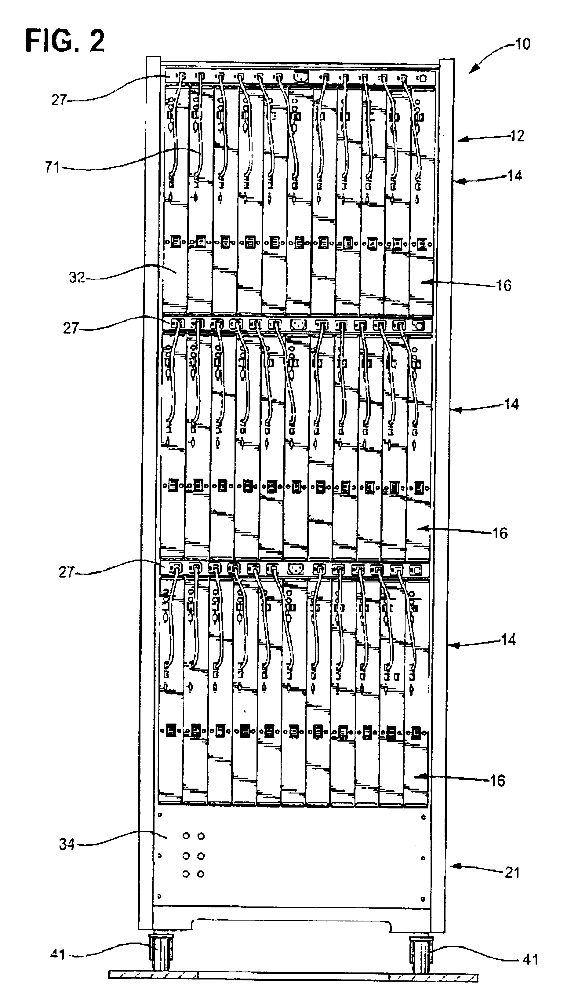
According to at least one of the disclosed embodiments of the present invention, there is provided a rack mounted system employing vertically mounted computer components in the form of blades for supporting circuit devices. The blades are mounted in a series of vertically spaced apart bays. In each bay, the vertically mounted blades are interconnected to a power distribution unit strip to cause the blades to be mounted compactly. Thus, a pair of sets of vertically mounted blades are attached to opposite sides of the power distribution unit within the same bay. Cooling fan units are positioned between each vertically spaced apart bays to provide vertical air flow through the system.
Referring now to FIGS. 1 through 21, there is illustrated one embodiment of a rack mounted system 10 according to the present invention. The rack mounted system 10 includes a rack housing 12 configured generally as a rectangular box having a plurality of vertical bays 14. The embodiment illustrated in the ...
PUM
 Abstract
Description
Claims
Application Information