Power distribution unit branch protection

a power distribution unit and branch protection technology, applied in emergency protective circuit arrangements, emergency protection circuit arrangements, relays, etc., can solve the problems of circuit breakers in pdus, affecting the operation of power distribution units, and increasing the cost of pdus. , to achieve the effect of reducing the size and cost of pdus, reducing heat loss, and fast trip tim

Inactive Publication Date: 2011-07-14
IBM CORP
View PDF13 Cites 46 Cited by
  • Summary
  • Abstract
  • Description
  • Claims
  • Application Information

AI Technical Summary

Benefits of technology

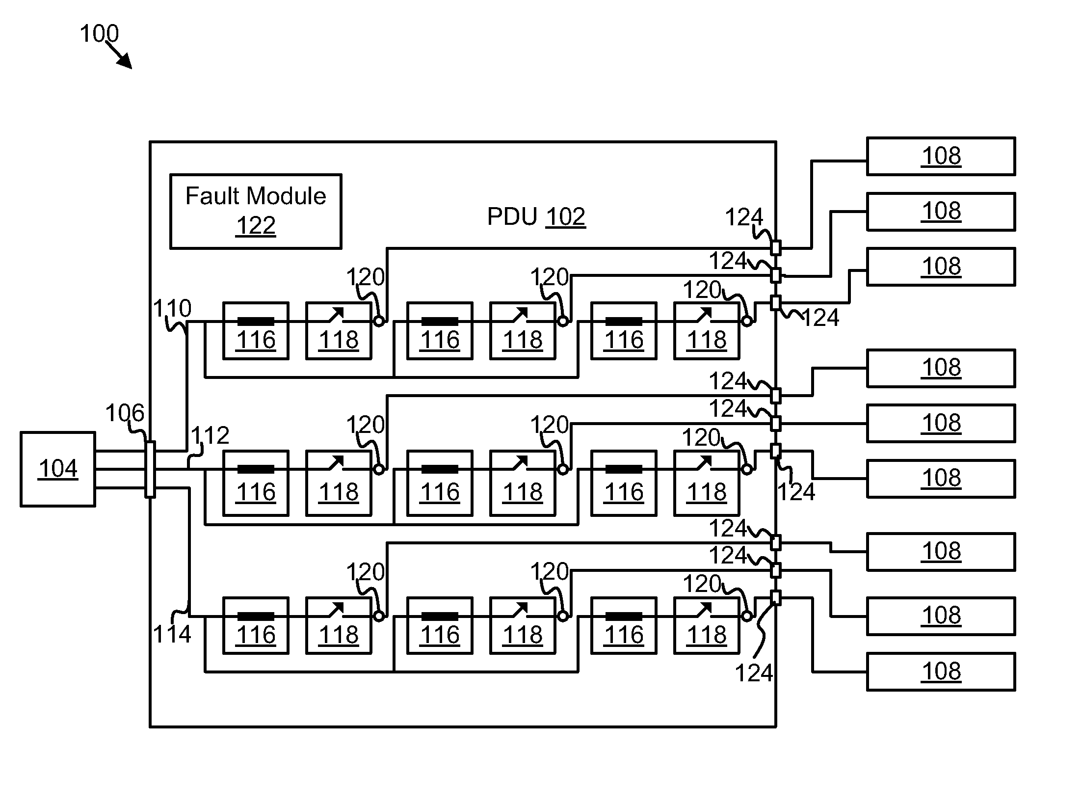
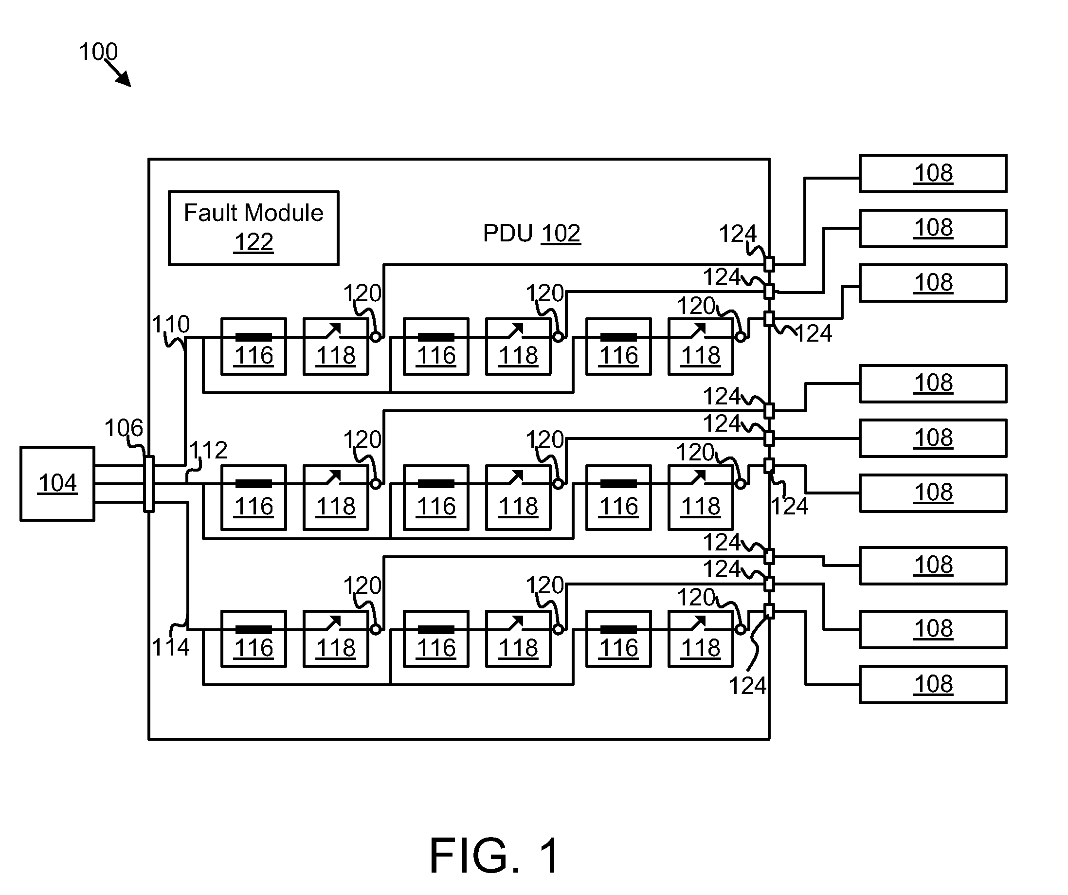
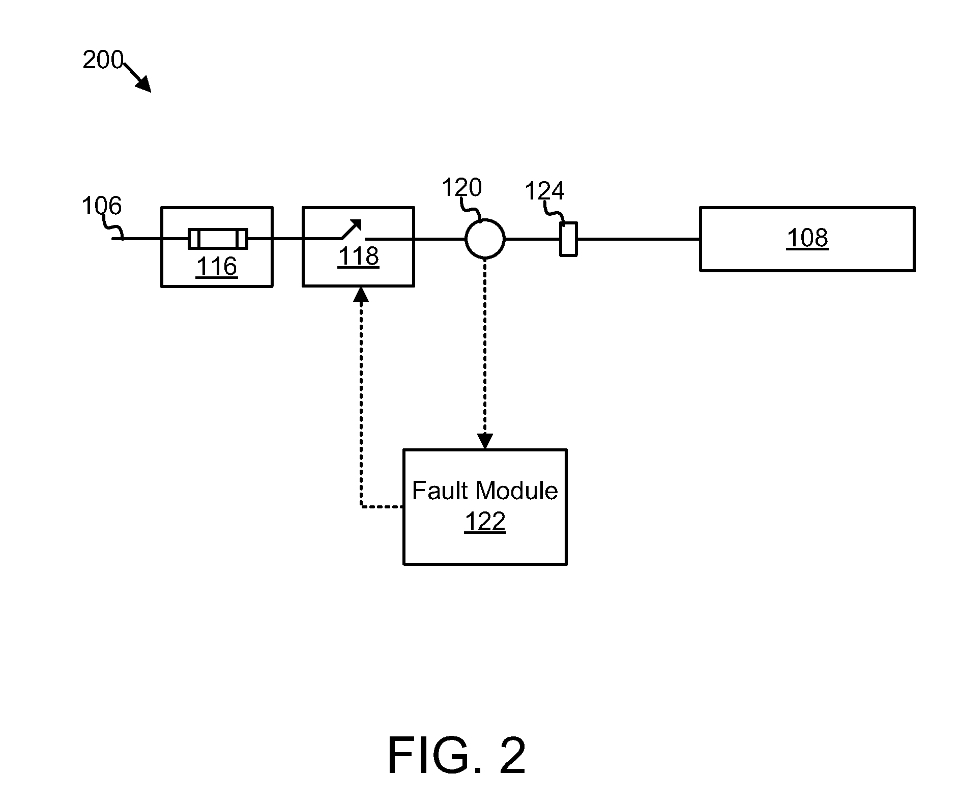
[0010]From the foregoing discussion, it should be apparent that a need exists for an apparatus and system that protect a PDU from electrical faults. Beneficially, such an apparatus, system, and method would generate little heat, have a fast trip time, be remotely resettable, and reduce sizes and costs of PDUs.

Problems solved by technology

Including circuit breakers in a PDU, however, has several negative effects.
For example, using circuit breakers increases the cost of the PDU.
If a separate circuit breaker is used for each outlet of a PDU, the circuit breakers increase the cost of the PDU dramatically.
This means that once a circuit breaker trips, the outlets protected by the circuit breaker cannot be used again until someone arrives on location and resets the circuit breaker.
This can extend power interruptions long after the overcurrent fault no longer exists.
High temperatures can affect the operation of a PDU itself, increase temperatures of other equipment around the PDU, and pose a safety threat.
Circuit breakers can also be rather bulky.
Larger PDUs require more material to manufacture, increasing material costs.
PDUs that are larger are also less flexible in use, requiring more space in what are often tight quarters.
Further, circuit breakers can take a long time to trip during overcurrent conditions.
Extended periods of overcurrent conditions can cause output voltages to sag and may have other negative effects on an electrical load that receives power from the PDU.
Using circuit breakers for PDU branch protection trades cost, convenience, heat, and size for safety.

Method used


Image

  • Power distribution unit branch protection
  • Power distribution unit branch protection
  • Power distribution unit branch protection

Examples


Embodiment Construction

[0051]As will be appreciated by one skilled in the art, aspects of the present invention may be embodied as a system, method or apparatus. Accordingly, elements of the present invention may take the form of an entirely hardware embodiment or an embodiment combining software and hardware aspects that may all generally be referred to herein as a “circuit,”“module” or “system.” Furthermore, aspects of the present invention may take the form of a computer program product embodied in one or more computer readable medium(s) having computer readable program code embodied thereon.

[0052]Many of the functional units described in this specification have been labeled as modules, in order to more particularly emphasize their implementation independence. For example, a module may be implemented as a hardware circuit comprising custom VLSI circuits or gate arrays, off-the-shelf semiconductors such as logic chips, transistors, or other discrete components. A module may also be implemented in progra...


PUM


Abstract

An apparatus and system are disclosed for protecting a power distribution unit from an electrical fault. A fuse interrupts a flow of electrical current in response to the electrical current rising above a current rating of the fuse. A current sensor measures the amplitude of the electrical current and outputs a current amplitude signal. A relay interrupts the flow of electrical current in response to an OFF signal. A fault module receives the current amplitude signal and sends the OFF signal to the relay in response to the amplitude of the electrical current exceeding a threshold value. The relay, the fuse, and the threshold value are selected so that a switching time of the relay is less than an opening time of the fuse for an amplitude of the electrical current between the threshold value and a maximum fault current value, so that the relay prevents the fuse from opening.

Description

BACKGROUND[0001]1. Field of the Invention[0002]This invention relates to power distribution units and more particularly relates to branch protection within power distribution units.[0003]2. Description of the Related Art[0004]Power distribution units (“PDUs”) are used to distribute electric power for electrically intensive applications such as computer data centers, industrial equipment, electric motors, and the like. PDUs typically have a safe grounding system and provide overcurrent protection using circuit breakers.[0005]Including circuit breakers in a PDU, however, has several negative effects. For example, using circuit breakers increases the cost of the PDU. If a separate circuit breaker is used for each outlet of a PDU, the circuit breakers increase the cost of the PDU dramatically.[0006]Additionally, if a circuit breaker trips, it must be physically reset, even after an overcurrent fault has been remedied. This means that once a circuit breaker trips, the outlets protected b...

Claims


Application Information

Patent Timeline
Patent Type & Authority Applications(United States)
IPC IPC(8): H02H3/08
CPCH02H3/08
Inventor DIMARCO, ROBERT A.DISHMAN, CECIL C.LINDFORS, EINO A.MALIK, RANDHIR S.
Owner IBM CORP
Why Eureka
Try Eureka