Multilevel inverter control schemes

a control scheme and multi-level technology, applied in the direction of dc-ac conversion without reversal, power conversion system, electrical apparatus, etc., can solve the problems of high switching power loss, complex and time-consuming, detailed optimal calculation of switching time based on harmonics elimination and harmonics minimization schemes, etc., to minimize an area difference and minimize the effect of area differen

Inactive Publication Date: 2005-03-15
SIEMENS VDO AUTOMOTIVE CORP
View PDF5 Cites 27 Cited by
  • Summary
  • Abstract
  • Description
  • Claims
  • Application Information

AI Technical Summary

Benefits of technology

It is a feature and advantage of the present invention to provide a method and system of near real time control of multilevel inverters.
In one embodiment of the present control schemes, a method for controlling a multilevel inverter includes but is not limited to determining at least a peak amplitude of a target waveform; determining a number of discrete steps to achieve the peak amplitude of the target waveform; calculating a plurality of switching angles to substantially minimize an area difference between the target waveform and a step signal of the multilevel inverter, in response to the number of discrete steps; and activating a plurality of voltage sources in response to the plurality of switching angles. In addition to the foregoing, other method embodiments are described in the claims, drawings, and text forming a part of the present application. In certain implementations involving a wide DC input voltage range, the disclosed methods may prove particularly useful.
In one or more various embodiments, related motorized vehicles and / or other systems include but are not limited to circuitry and / or programming for effecting the herein-referenced method embodiment(s); the circuitry and / or programming can be virtually any combination of hardware, software, and / or firmware configured to effect the foregoing-referenced method embodiments depending upon the design choices of the system designer.
In another embodiment of the present control schemes, a multilevel inverter control system includes but is not limited to means for determining at least a peak amplitude of a target waveform; means for determining a number of discrete steps to achieve the peak amplitude of the target waveform; means, responsive to the number of discrete steps, for calculating a plurality of switching angles to substantially minimize an area difference between the target waveform and a step signal of the multilevel inverter; and means for activating a plurality of voltage sources in response to the plurality of switching angles. In addition to the foregoing, other system embodiments are described in the claims, drawings, and text forming a part of the present application. In certain implementations involving a wide DC input voltage range, the disclosed systems may prove particularly useful.
In another embodiment of the present control schemes, a power-related device includes but is not limited to means for determining at least a peak amplitude of a target waveform; means for determining a number of discrete steps to achieve the peak amplitude of the target waveform; means for calculating a plurality of switching angles based on at least one of a frequency and the number of discrete steps to achieve the peak amplitude of the target waveform; and means for activating a plurality of voltage sources in response to the plurality of switching angles. In addition to the foregoing, other system embodiments are described in the claims, drawings, and text forming a part of the present application. In certain implementations involving a wide DC input voltage range, the disclosed systems may prove particularly useful.
In another embodiment of the present control schemes, a multilevel inverter control system includes but is not limited to a step number determination module; and a switch angle determination module having logic configured to substantially minimize an area difference between a target waveform and a step signal of a multilevel inverter. In addition to the foregoing, other system embodiments are described in the claims, drawings, and text forming a part of the present application. In certain implementations involving a wide DC input voltage range, the disclosed systems may prove particularly useful.

Problems solved by technology

There are two main issues amongst many others in design of such an inverter-high switching power loss and high electric magnetic interference (EMI).
Detailed optimal calculation of switching time based on the mathematical theory of harmonics elimination and harmonics minimization schemes is complicated and time consuming.
Because the related art schemes of multilevel inverter control typically use look-up tables at run time, such related art schemes are unresponsive to real time changes involving multilevel inverters.
In addition, due to the fact that the control equations are non-linear and numerous, real time application of such equations is not generally practicable.

Method used


Image

  • Multilevel inverter control schemes
  • Multilevel inverter control schemes
  • Multilevel inverter control schemes

Examples


Embodiment Construction

In the following description, certain specific details are set forth in order to provide a thorough understanding of the various embodiments of the subject matter described herein. However, one skilled in the art will understand that the subject matter described herein may be practiced without these details. In other instances, well-known structures associated with electrical power devices and / or power transfer devices have not been shown or described in detail to avoid unnecessarily obscuring descriptions of the embodiments of the subject matter described herein.

Unless the context requires otherwise, throughout the specification and claims which follow, the word “comprise” and variations thereof, such as, “comprises” and “comprising” are to be construed in an open, inclusive sense, that is as “including, but not limited to.”

The headings provided herein are for convenience only and do not interpret the scope or meaning of the claimed invention.

I. Sub-Optimal Switching Algorithm
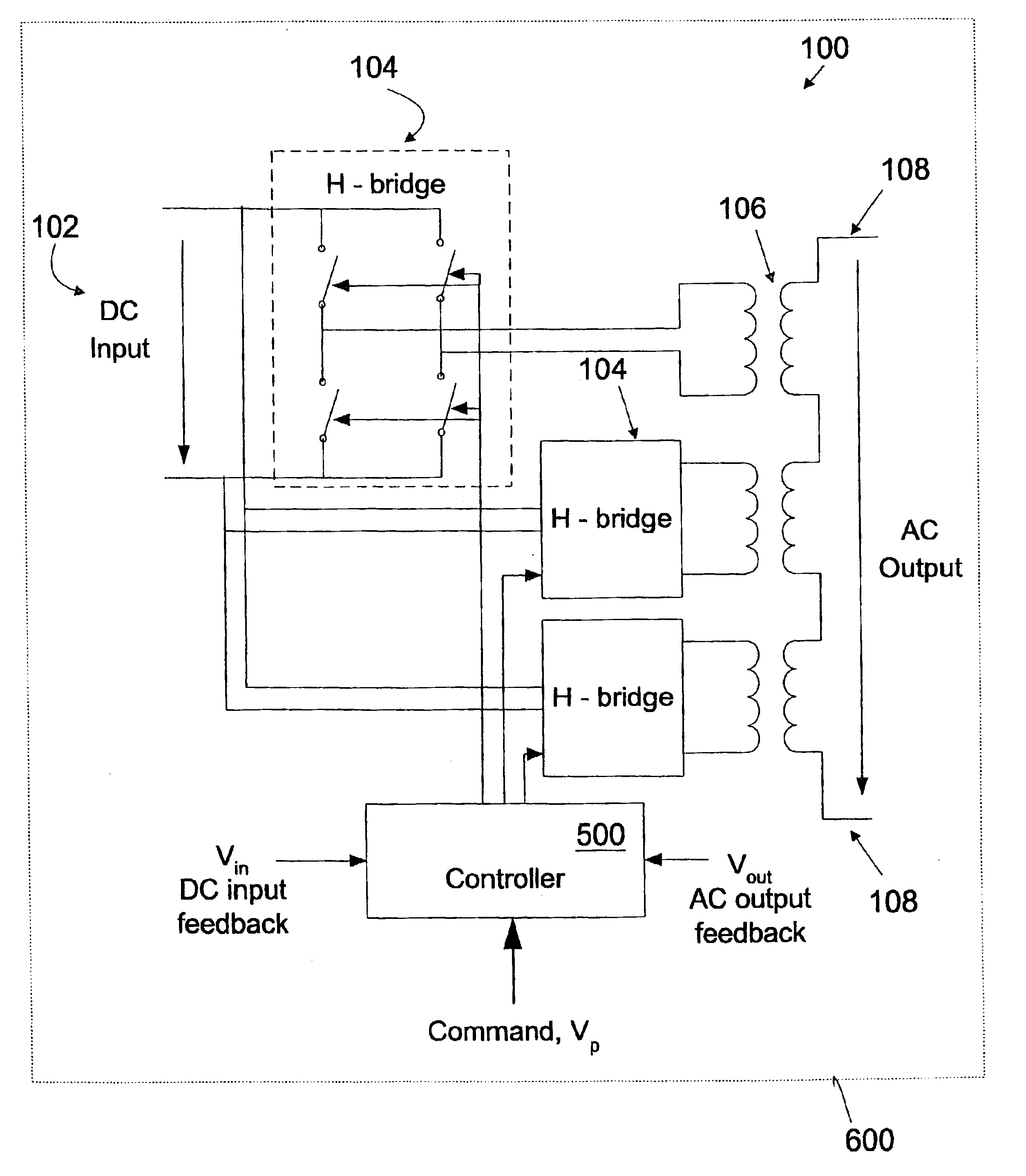
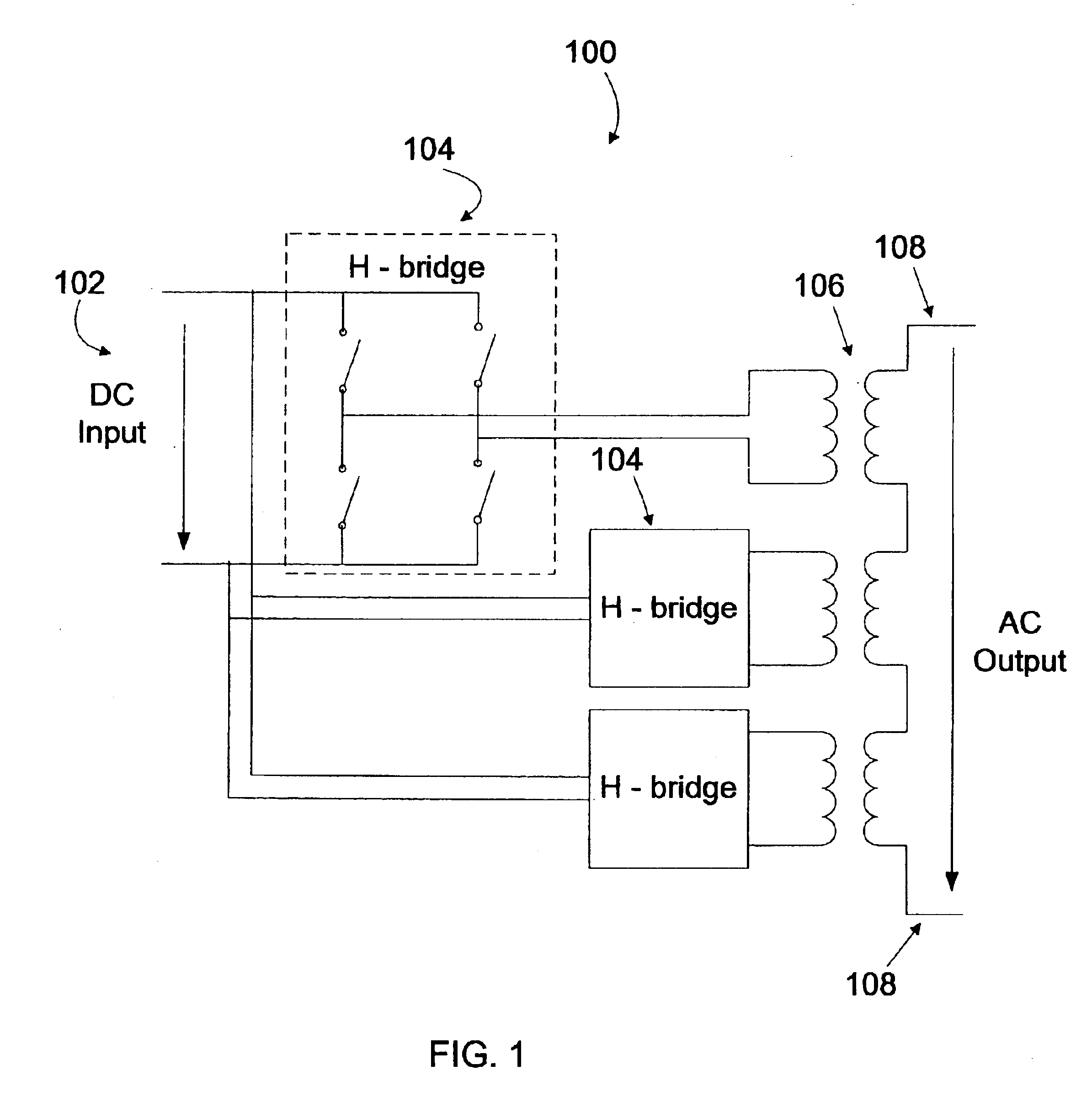
FIG. ...


PUM


Abstract

A multilevel inverter control system having logic configured to substantially minimize and area between a target waveform and a step signal of a multilevel inverter.

Description

BACKGROUND OF THE INVENTION1. Field of the InventionThe present invention relates generally to the field of direct current-to-alternating current (DC / AC) inverters, and more particularly to control schemes for a multilevel inverter.2. Description of the Related ArtA DC / AC inverter changes DC power into AC power. In a PWM (pulse width modulation) controlled inverter, DC voltage is “chopped” into pulses. The mean value of the pulses follows a sinusoidal waveform. Depending on the power rating of the inverter, the switching frequency can range from a few kHz to a few tens of kHz. There are two main issues amongst many others in design of such an inverter-high switching power loss and high electric magnetic interference (EMI).One of the alternatives to PWM controlled inverter schemes is to use a multilevel voltage source inverter. A multilevel inverter is a practical approach when an output transformer is required at the load side for safety reasons. Standard products with power ratings...

Claims


Application Information

Patent Timeline
Patent Type & Authority Patents(United States)
IPC IPC(8): H02M7/48H02M7/49
CPCH02M7/49
Inventor CHENG, BINGHUANG, FENGTAI
Owner SIEMENS VDO AUTOMOTIVE CORP
Why Eureka
Try Eureka