
Echo canceling method, echo canceller and voice switch

a technology of echo canceller and voice switch, which is applied in the direction of line-transmission, electrical equipment, interconnection arrangements, etc., and can solve the problem of howling in some cases

Inactive Publication Date: 2005-03-15
PANASONIC INTELLECTUAL PROPERTY CORP OF AMERICA
View PDF24 Cites 35 Cited by
  • Summary
  • Abstract
  • Description
  • Claims
  • Application Information

AI Technical Summary

Benefits of technology

The present invention relates to an echo canceller for improving speech quality in a digitized input signal. The invention uses an adaptive filter to cancel out echoes caused by the input signal. The invention includes a method for updating the adaptive filter using a pseudo whitened signal and an echo replica signal. The invention also includes a speech communication state determination system that can determine the current speech communication state based on the results of judging the presence of a near-end or far-end speaker's voice. The invention can also control the attenuation of the speaker's voice based on the speech communication state. The technical effects of the invention include improved speech quality, reduced echoes, and improved speech communication state determination.

Problems solved by technology

Even when learning is sufficiently performed, therefore, howling may, in some cases, occur.

Method used


Image

  • Echo canceling method, echo canceller and voice switch
  • Echo canceling method, echo canceller and voice switch
  • Echo canceling method, echo canceller and voice switch

Examples


first embodiment

[1] Description of First Embodiment

Referring now to FIGS. 5 to 12, a first embodiment of the present invention will be described.

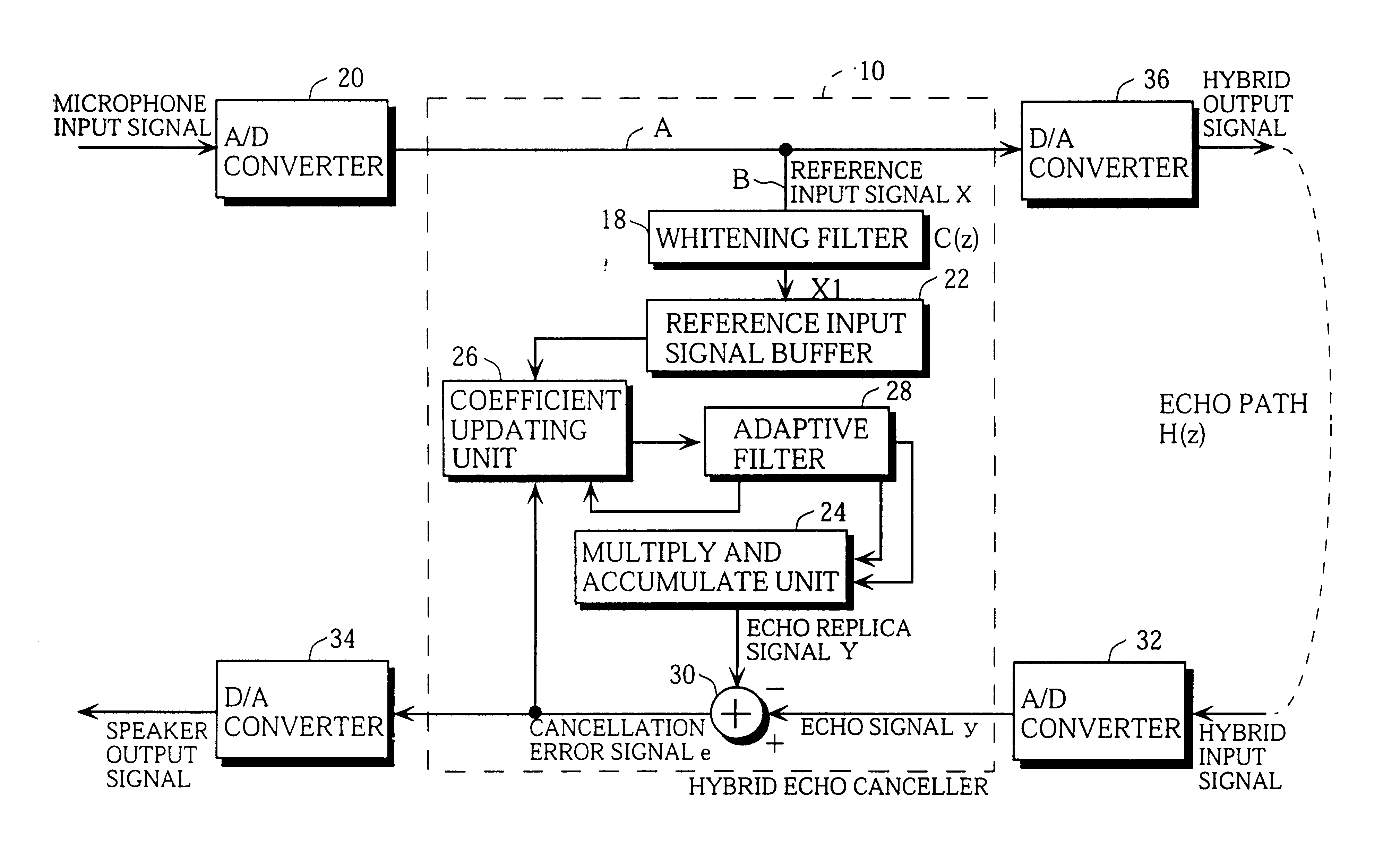
FIG. 5 illustrates an echo canceller 10 and its peripheral circuits.

The echo canceller 10 comprises a CPU 12, a ROM 14, and a RAM 16.

The ROM 14 stores a program for controlling the operation of the echo canceller 10, including the foregoing equations for calculation (1) to (3), and a previously set data. The data stored in the ROM 14 include the number of taps N in an adaptive filter 28 (described later), a step gain μ, and so forth.

The RAM 16 temporarily stores data such as a calculated value obtained by an operation in the CPU 12. The data stored in the RAM 16 include an echo signal y, an echo replica signal Y, an adaptive filter coefficient, a value x in a reference input signal buffer, a cancellation error signal e, and so forth. The number of taps N in the adaptive filter and the step gain μ may be stored in the RAM 16.

The CPU 12 is operated using the...

second embodiment

[2] Description of Second Embodiment

Referring now to FIGS. 13 to 15, a second embodiment of the present invention will be described.

FIG. 13 illustrates the configuration of a voice switch.

The voice switch comprises a near-end speaker's voice detector (near-end speaker's voice judgment means) 101 for detecting a near-end speaker's voice which is sent to a transmission path 111, an attenuator 102 provided in the transmission path 111, a far-end speaker's voice detector (far-end speaker's voice judgment means) 103 for detecting a far-end speaker's voice which is sent to a receiving path 112, an attenuator 104 provided in the receiving path 112, and a control unit 105 for respectively controlling the attenuators 102 and 104 on the basis of both the speech detectors 101 and 103.

The near-end speaker's voice detector 101 judges whether the near-end speaker's voice is present or absent, and sends the result of the judgment to the control unit 105. For example, when the power average of a vo...


PUM


Abstract

A digitized input signal is sampled, to obtain a reference input signal. The reference input signal is spuriously whitened, to obtain a pseudo whitened signal. An echo replica signal is generated on the basis of the pseudo whitened signal and an adaptive filter coefficient. A cancellation error signal is obtained on the basis of an echo signal and the echo replica signal. The adaptive filter coefficient is updated on the basis of the cancellation error signal, the adaptive filter coefficient, and the pseudo whitened signal.

Description

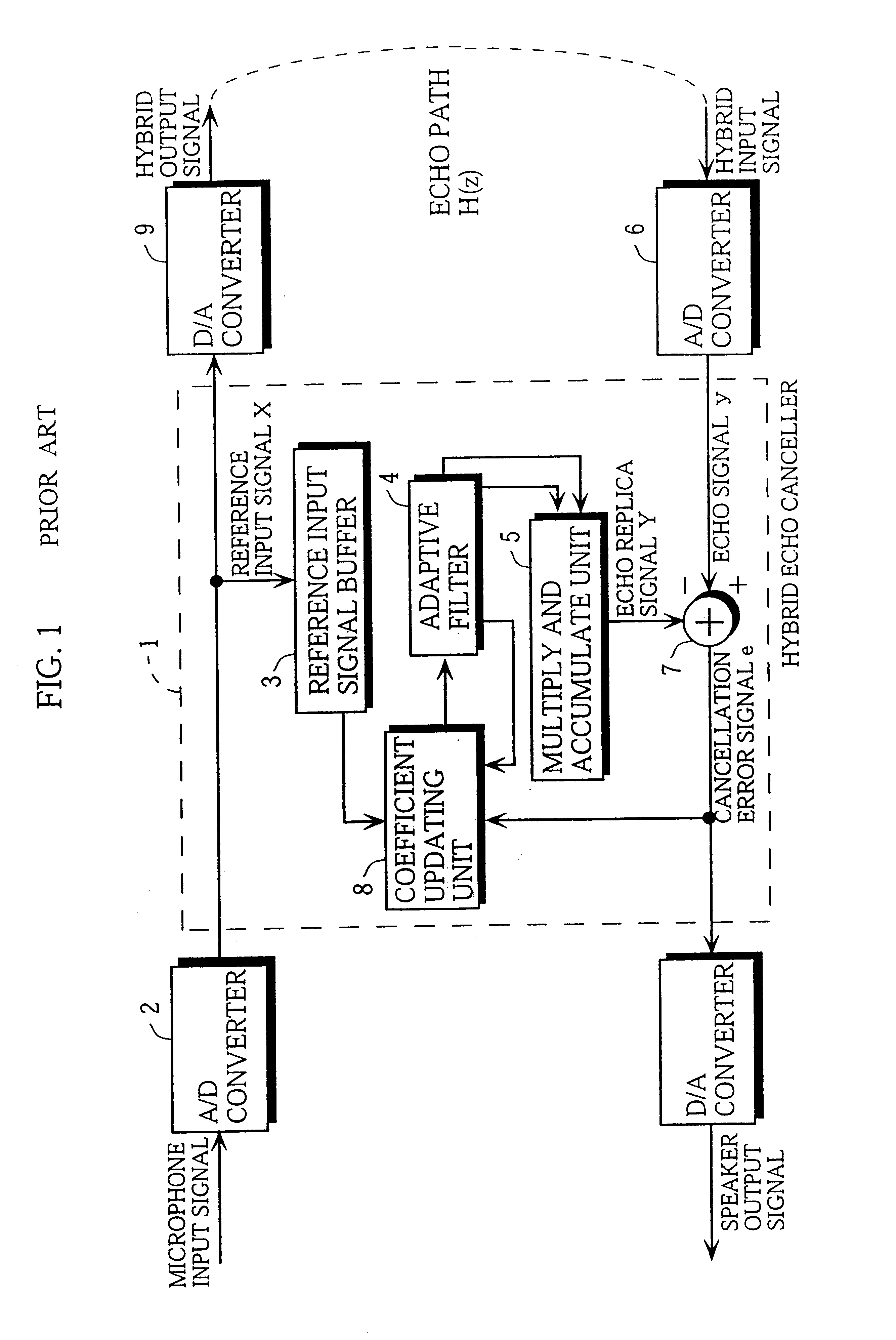
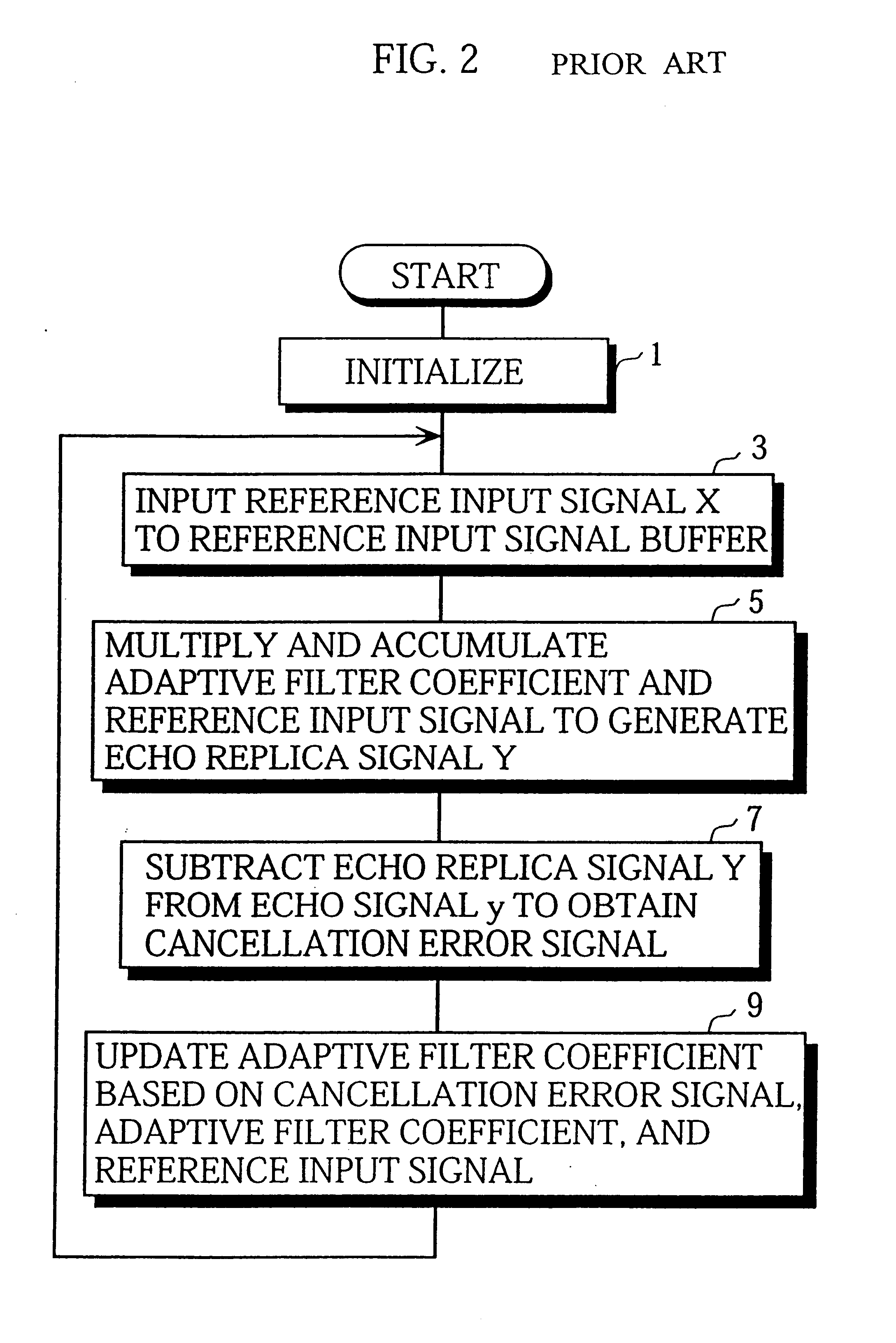
TECHNICAL FIELDThe present invention relates generally to an echo canceling method and an echo canceller, and more particularly, to an echo canceling method and an echo canceller which are utilized in order to realize full duplex in a hands-free telephone set or a television conference, for example.Furthermore, the present invention relates to a voice switch used for a hands-free speech communication system capable of carrying out telephone conversation using a speaker and a microphone.BACKGROUND ART[1] In an echo canceller utilized in order to realize full duplex in a hands-free telephone set, a television conference, and so forth, an adaptive filter coefficient has been conventionally updated using an alternate voice, to estimate an impulse response of an echo path. As this estimation algorithm, the Normalized Least Mean Square Method (the NLMS Method) having a relatively small amount of operation has been frequently used.FIG. 1 illustrates an example of a conventional echo cancel...

Claims


Application Information

Patent Timeline
Patent Type & Authority Patents(United States)
IPC IPC(8): H04B3/23H04B3/20H04M1/00H04M9/00H04M9/08
CPCH04B3/23
Inventor OKUDA, KOZO
Owner PANASONIC INTELLECTUAL PROPERTY CORP OF AMERICA
Learn More