Picture holding system

a picture and holding system technology, applied in the field of frontloading picture holding system, can solve the problems of difficult, inconvenient and often complicated to load or unload pictures in the picture holding system, and takes unnecessary time and effort in detachment, and achieves the effect of convenient and convenien

Inactive Publication Date: 2005-03-22
KIM PAUL T
View PDF18 Cites 39 Cited by
  • Summary
  • Abstract
  • Description
  • Claims
  • Application Information

AI Technical Summary

Benefits of technology

The present invention contrives to solve the disadvantages of the prior art. Accordingly, an object of the invention is to provide a picture holding system such that a picture can be loaded and unloaded from the picture holding system in an easy and convenient way.
Since the present invention allows loading and unloading the picture from the front of the system, the picture holding system provides a structure such that the picture can be framed frontally in any shape of frame body and therefore this system can be integrated to various ornamental objects that are unable to load the picture from the rear and thus offers wide variety of picture frame designs.
The advantages of the present invention are: (1) a picture holding system having an easy, convenient and simple structure to load a picture; (2) the picture holding system having an easy, convenient and simple structure to unload the picture; (3) the picture holding system having a structure that can be easily adapted to various ornamental objects; and (4) the picture holding system having a simple structure that needs fewer parts to manufacture.

Problems solved by technology

However, conventional picture holding systems lack in functions detaching the transparent plate from a support frame in an easy and convenient way, and thus made it difficult, inconvenient and often complicated to load or unload the picture in the picture holding system.
Typical structure of the conventional picture holding systems is to use pivoting fasteners in the backside of the picture holding system and it takes unnecessary time and effort in detaching the transparent plate or the picture, and sometimes, a user has to shake the whole frame body in order to pull out the transparent plate or the picture from the picture holding system.

Method used


Image

  • Picture holding system
  • Picture holding system
  • Picture holding system

Examples


Embodiment Construction

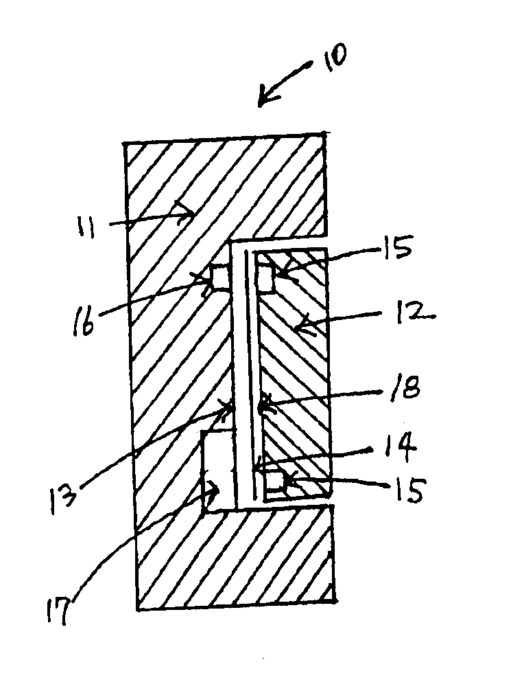
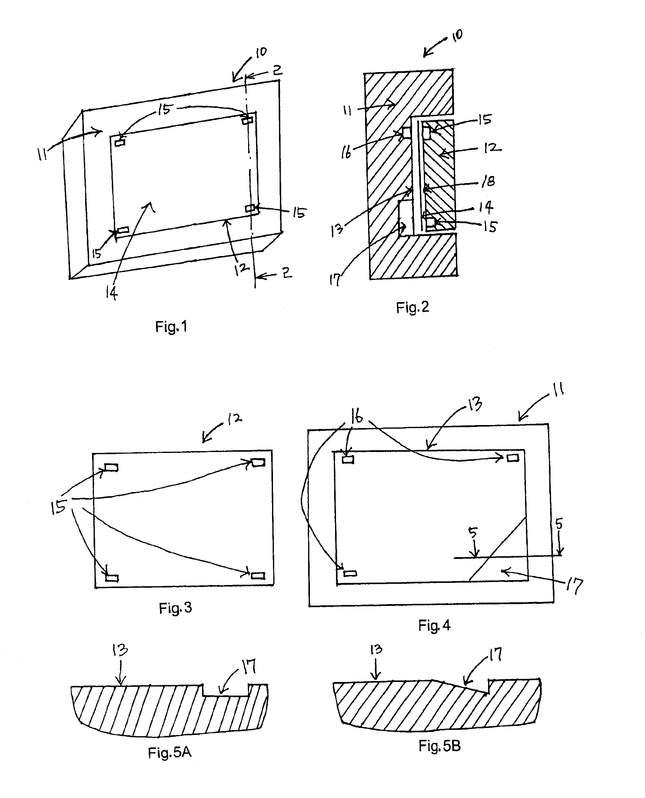
FIGS. 1 and 2 show a picture holding system 10 according to the present invention. The picture holding system 10 includes a base 11 and a transparent plate 12 to display a picture 14. The base 11 has a support surface 13 that accepts the transparent plate 12. The support surface 13 supports the picture 14 between the transparent plate 12 and itself. The transparent plate 12 has four plate magnets 15 that are embedded at four perimetric positions of the rear surface 18 of the transparent plate 12 as further shown in FIG. 3. The support surface 13 has three surface magnets 16 that are fixed to three perimetric positions of the support surface 13. The one remaining perimetric position was taken by an edge 17 and recessed into the rearward of the base 11 as further shown in FIGS. 4, 5A and 5B. The surface of the recessed edge 17 may either slope down from the support surface 13 as shown in FIG. 5B or be flat as shown in FIG. 5A. The number of magnet is variable based on the weight, size...


PUM


Abstract

A front-loading picture holding system comprising a transparent plate, a support surface supporting the transparent plate and a picture between the transparent plate and the support surface, and a base that receives the transparent plate and the support surface is provided. Magnets are fixed to the transparent plate and the support surface. The support surface has an edge that is located near the perimeter of the support surface and recessed into the rearward of the base. Ferromagnetic body may be used instead of the magnet either in the transparent plate or in the support surface. The transparent plate is removably attached to the support surface by magnetic force between the plate magnet and the corresponding surface magnet, and the transparent plate may be pulled apart by pressing the transparent plate over the edge and pivoting the transparent plate over the support surface.

Description

BACKGROUND OF THE INVENTIONThe present invention relates to a front-loading picture holding system. More particularly, the invention relates to a picture holding system that is easy and convenient in loading and unloading to and from the front of a picture frame body rather than from the rear of the frame.Picture holding systems are widely used by many people in our life. However, conventional picture holding systems lack in functions detaching the transparent plate from a support frame in an easy and convenient way, and thus made it difficult, inconvenient and often complicated to load or unload the picture in the picture holding system.Typical structure of the conventional picture holding systems is to use pivoting fasteners in the backside of the picture holding system and it takes unnecessary time and effort in detaching the transparent plate or the picture, and sometimes, a user has to shake the whole frame body in order to pull out the transparent plate or the picture from the...

Claims


Application Information

Patent Timeline
Patent Type & Authority Patents(United States)
IPC IPC(8): A47G1/06A47G1/00A47G1/14
CPCA47G1/06A47G1/14A47G2001/0672A47G2001/0666
Inventor KIM, PAUL T.
Owner KIM PAUL T
Why Eureka
Try Eureka