
Concrete chute apparatus

a chute and concrete technology, applied in cement mixing apparatuses, building materials handling, construction, etc., can solve the problems of hazard to drivers behind, cement debris may fall out of the chute accidentally, and cement debris may form on the chute, so as to prevent road hazards, prevent property damage, injury or death, and operate safely.

Inactive Publication Date: 2005-03-22
THOMPSON RAYMOND F
View PDF6 Cites 28 Cited by
  • Summary
  • Abstract
  • Description
  • Claims
  • Application Information

AI Technical Summary

Benefits of technology

To attain this, the present invention essentially comprises a plate attached to the rotatable section of a cement truck's chute, such that the plate blocks the opening created when the rotatable section is rotated up, thereby preventing cement residue or debris from falling from the truck.
It is therefore an object of the present invention to provide a new and improved concrete chute apparatus suitable for use on concrete delivery vehicles, concrete mixers, and other reservoirs of flowable materials, such as cement, uncured concrete, gunite, and gravel, which apparatus prevents the unwanted discharge of material from an articulated chute and prevents debris from falling from such a vehicle while it is moving on roads or highways, thereby preventing road hazards, property damage, injury, or death.
It is a further object of this invention to provide a concrete chute apparatus that is completely automatic to the extent that its operation requires no extra action by a driver or operator. Furthermore, an object of the invention is to provide an apparatus having no moving parts, which apparatus is in proper placement with respect to the chute at all times. It is therefore another object of this invention to provide an apparatus that is rugged and reliable, and which may be operated safely, having no pinch points, which could injure an operator.
It is another object of the present invention to provide a new and improved concrete chute apparatus that may be permanently attached to a chute, is simple and inexpensive to manufacture, easy to install, has a long useful life, and may be easily and efficiently manufactured and marketed.
An even further object of the present invention is to provide a new and improved concrete chute apparatus that has a low cost of manufacture with regard to both materials and labor, and which accordingly is then susceptible of low prices of sale to the consuming public, thereby making such concrete chute apparatus economically available to the buying public.
It is still another object of the present invention to provide an apparatus that is readily installable and substantially maintenance free.

Problems solved by technology

Cement debris may form on the chute after the cement is poured.
This cement debris may accidentally fall out of the chute while the truck is returning from the construction site.
This may be a hazard to drivers behind the truck and may form undesirable deposits on the roads.
This concrete residue creates environmental problems, as it kills plants, contaminates waterways, and is a source of injury to humans and animals.
However, Jamieson '461 does not make any provision for those construction sites where there would be no room for the apparatus below the chute.
Further, Jamieson '461 requires numerous, moving parts.
For example, Stinson '299 may inadvertently be placed in the closed position while dispensing cement, thus Stimson '299 has the potential to block the chute while cement is being dispensed, which could cause cement to flow over the sides of the chute.
Further, such a chute cap may become lost, as it is not fastened to the chute while not in use.
However, Cronquist '398 does not make any provision for those construction sites where there would be no room for the apparatus below the chute.
While the above-described devices fulfill their respective, particular objectives and requirements, the aforementioned patents do not describe a device that is positioned above the chute while cement is dispensing.
Further, the aforementioned patents do not describe a device that requires no moving parts.
Furthermore, the above-mentioned patents do not satisfy the additional limitations of the prior art set forth above.

Method used


Image

  • Concrete chute apparatus
  • Concrete chute apparatus
  • Concrete chute apparatus

Examples


Embodiment Construction

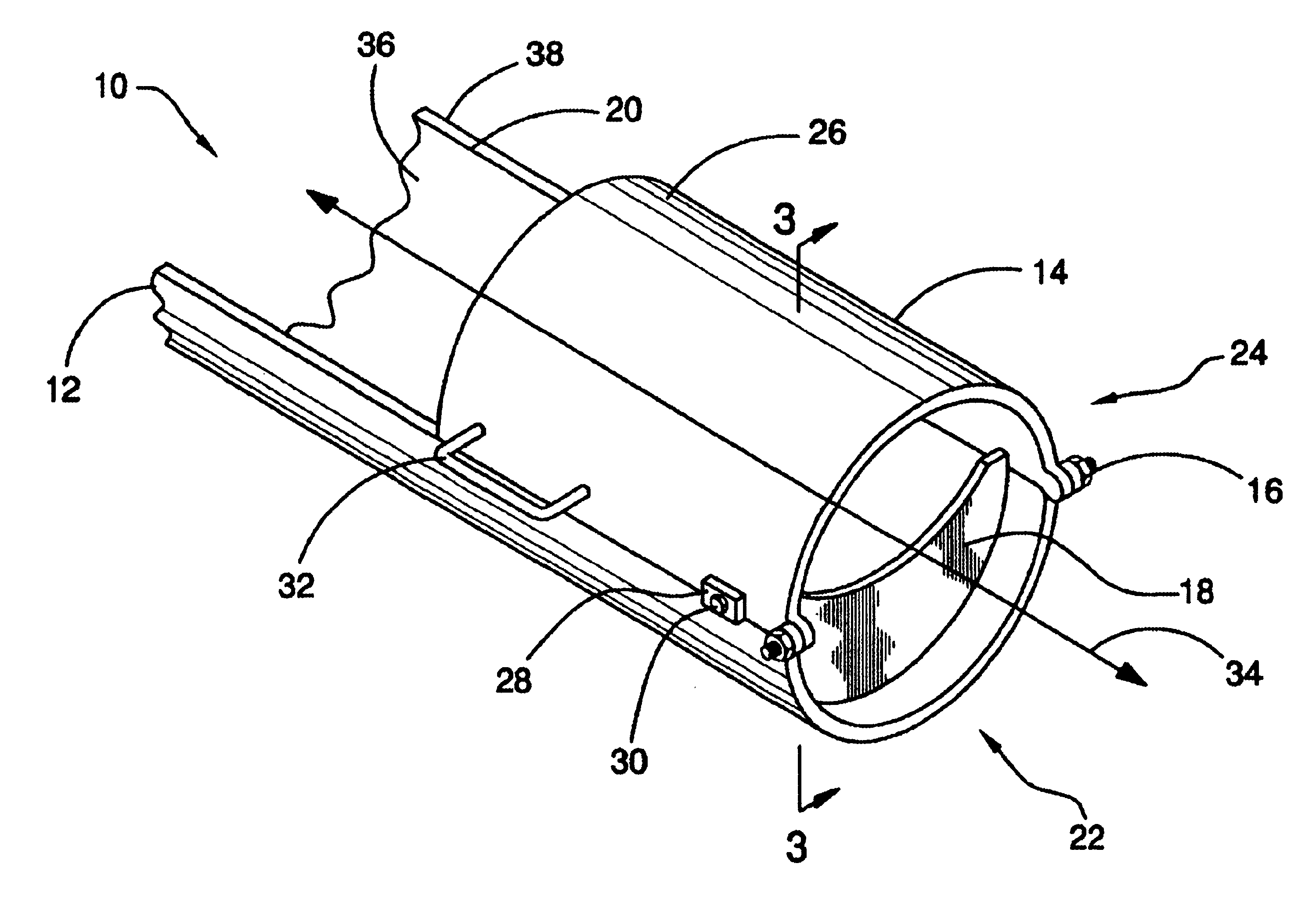
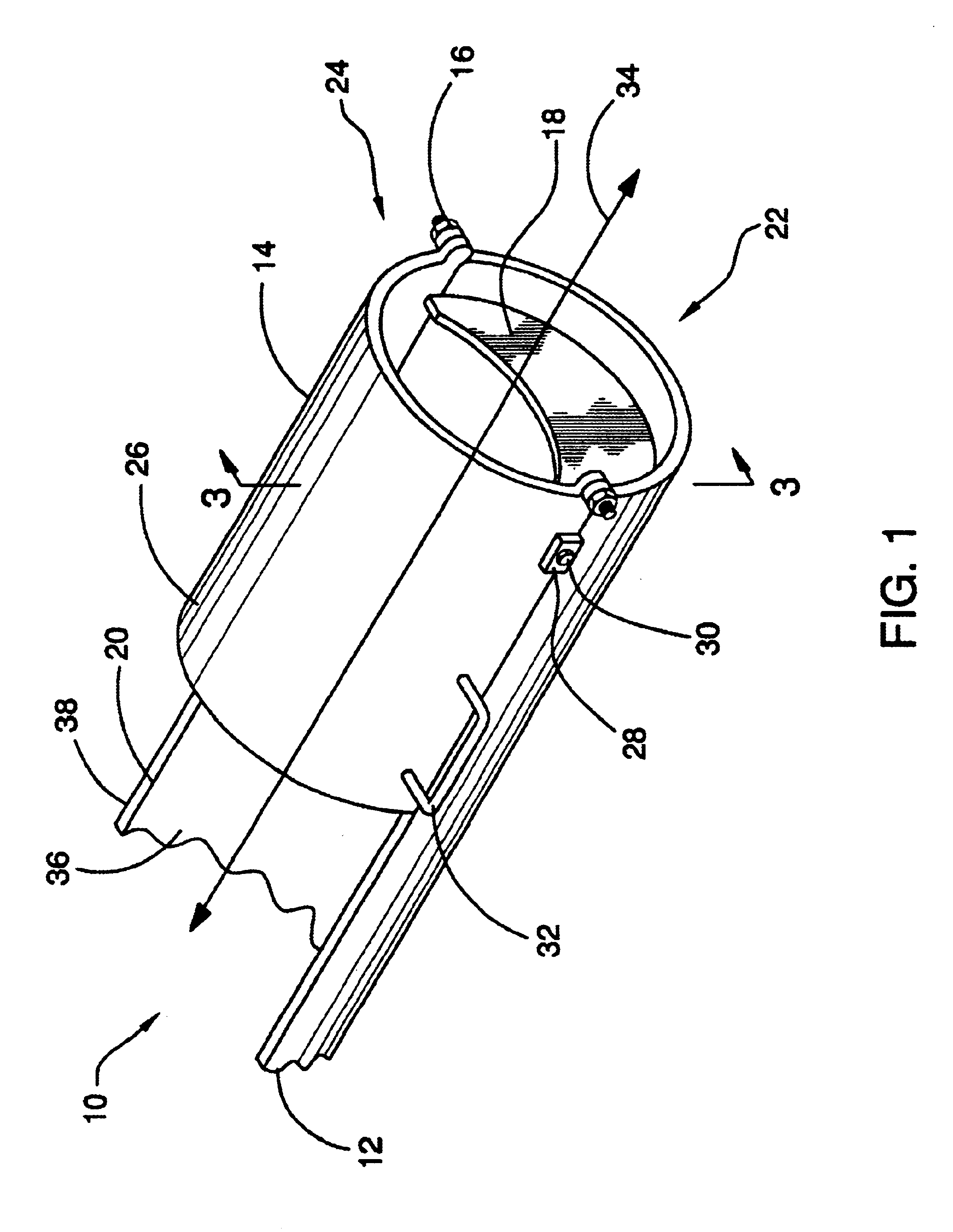
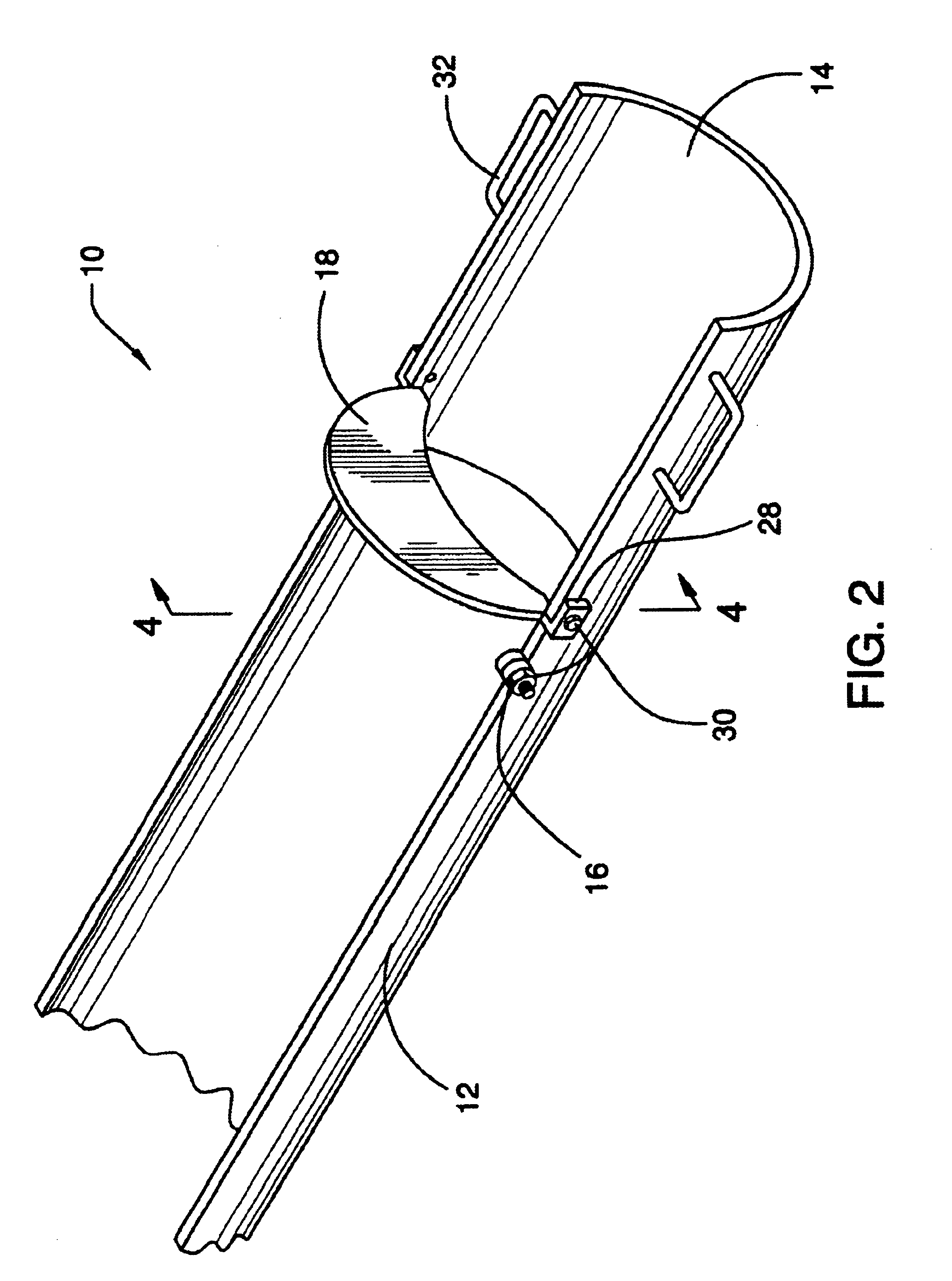
Referring now to the drawings, and particularly to FIGS. 1-4, a concrete discharge chute employing a preferred embodiment of the concrete chute apparatus of the present invention is shown and generally designated by the reference numeral 10.

In FIG. 1, a concrete discharge chute 10 is shown Concrete discharge chute 10 is arranged in cooperation with a conventional cement truck (not shown) and includes a main chute section 12 to which is hingeably coupled to over-chute section 14. Main chute section 12 and over-chute section 14 form an elongated chute having a concave interior through which cement can be dispensed when over-chute section 14 is in the down position. Main chute section 12 has a distal end 22 and a proximal end 20, where the proximal end is that end closest to the cement truck. Similarly, over-chute section 14 has a distal end 26 and a proximal end 24, where the distal end is that end furthest from the truck when over-chute section 14 is in its down position. The chute s...


PUM

PropertyMeasurementUnit
Shapeaaaaaaaaaa

Abstract

A concrete chute apparatus for preventing the accidental discharge of cement residue from the chute of a cement truck while the truck is moving is disclosed. To attain this, an abutment plate obstructs the opening of a cement truck caused by the folding of an articulated chute. In an embodiment, an abutment plate is rigidly affixed to an over-chute section of the articulated chute such that the plate obscures the concrete path when the over-chute section is rotated to the up position.

Description

BACKGROUND OF THE INVENTION1. Field of the InventionThe present invention relates to an apparatus for use with cement trucks. More particularly, this invention relates to a new and improved concrete chute apparatus used to prevent accidental discharge of cement from cement trucks while the truck is moving.2. Description of the Related ArtThis invention relates generally to an apparatus for blocking the cement discharge path found on cement trucks, thus preventing the road hazards, property damage, and personal injury caused by debris falling from cement truck chutes.Cement trucks typically have chutes which are used to pour cement at a construction site. Cement debris may form on the chute after the cement is poured. This cement debris may accidentally fall out of the chute while the truck is returning from the construction site. This may be a hazard to drivers behind the truck and may form undesirable deposits on the roads.In order to avoid the cement debris from falling out of the...

Claims


Application Information

Patent Timeline
IPC IPC(8): B65G11/20B65G11/00E04G21/04B28C5/08B28C5/42
CPCB28C5/0818B28C5/4251E04G21/04B65G11/206B28C5/4262E04G2021/049
Inventor THOMPSON, RAYMOND F.
Owner THOMPSON RAYMOND F
Features
  • Generate Ideas
  • Intellectual Property
  • Life Sciences
  • Materials
  • Tech Scout
  • Unparalleled Data Quality
  • Higher Quality Content
  • 60% Fewer Hallucinations
Learn More