Lighting system incorporating programmable video feedback lighting devices and camera image rotation

Inactive Publication Date: 2005-03-22
BELLIVEAU RICHARD S
View PDF10 Cites 11 Cited by
  • Summary
  • Abstract
  • Description
  • Claims
  • Application Information

AI Technical Summary

Benefits of technology

In this way the performer's image can also be captured by the camera. The performer's image can be incorporated into the video feedback art produced by the IPLD of the invention. It is also possible to mix content (such as video stills or animation) into the feedback art. The content as provided by memory of the IPLD or the content as provided over the communications system as received by the communications port of the IPLD may be simultaneously projected alon

Problems solved by technology

The work of adjusting or programming the parameters to the desired v

Method used


Image

  • Lighting system incorporating programmable video feedback lighting devices and camera image rotation
  • Lighting system incorporating programmable video feedback lighting devices and camera image rotation
  • Lighting system incorporating programmable video feedback lighting devices and camera image rotation

Examples


Example

DETAILED DESCRIPTION OF THE DRAWINGS

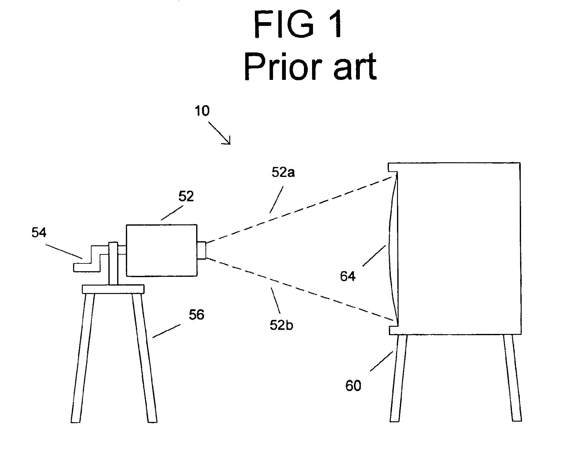
FIG. 1 shows a prior art video feedback system 10. The prior art video feedback system 10 includes a video camera 52 mounted to a crank handle 54 that is rotatably mounted to a tripod 56, so that the crank handle 54 can rotate with respect to the tripod 56 The crank handle 54 allows the camera 52 to be rotated on an optical axis of the camera 52. The camera 52 has it image field shown by dashed lines 52a and 52b. The camera 52 is centered to capture an image of the picture screen or the picture tube 64 of the monitor or television 60. The camera 52 is mounted to a tripod 56 so that the center of the optical field the camera 52 can be centered horizontally and vertically with the center of the picture tube 64. The camera's video output signal is routed with a video cable to the video input signal of the monitor 60 (not shown for simplification). The desired video feed back art is created when the camera's image field is rotated by physically rotati...


PUM


Abstract

A lighting system is disclosed comprising a plurality of image projection lighting devices including a first image projection lighting device, a central controller, and a communications system which permits the central controller to communicate with the plurality of image projection lighting devices. The first image projection lighting device is comprised of a camera, and a light valve, wherein the light valve is used to project a first projected image onto a projection surface. The camera of the first image projection light device can capture at least a portion of the first projected image projected from the light valve to form a first captured image. At least a portion of the first captured image is projected as a second projected image by the first image projection lighting device onto the projection surface creating a video feedback loop.

Description

FIELD OF THE INVENTIONThis invention relates to improved methods and apparatus concerning lighting systems.BACKGROUND OF THE INVENTIONLighting systems in the prior art are typically formed by interconnecting, via a communications system, a plurality of lighting fixtures and providing for operator control of the plurality of lighting fixtures from a central controller. Such lighting systems may contain multiparameter light fixtures, which illustratively are light fixtures having two or more individually remotely adjustable parameters such as focus, color, image, position, or other light characteristics. Multiparameter light fixtures are widely used in the lighting industry because they facilitate significant reductions in overall lighting system size and permit dynamic changes to the final lighting effect. Applications and events in which multiparameter light fixtures are used to great advantage include showrooms, television lighting, stage lighting, architectural lighting, live conc...

Claims


Application Information

Patent Timeline
IPC IPC(8): H04N13/00H04N5/74H04N17/00H04N9/12
CPCH04N13/0459H04N9/3194H04N9/3147H04N5/7416H04N9/12H04N13/363
Inventor BELLIVEAU, RICHARD S.
Owner BELLIVEAU RICHARD S
Why Eureka
Try Eureka