Illumination system particularly for EUV lithography

a technology of euv lithography and lithography, which is applied in the direction of lighting and heating equipment, instruments, and handling using diaphragms/collimeters, etc., can solve the problems of synchrotron radiation interference effects

Inactive Publication Date: 2001-03-06
CARL ZEISS SMT GMBH
View PDF10 Cites 283 Cited by
  • Summary
  • Abstract
  • Description
  • Claims
  • Application Information

AI Technical Summary

Problems solved by technology

In the case of undulator sources, the electrons in the undulator are subjected to a magnetic field with shorter periods and smaller magnetic field of the deflection pole than in the case of the wiggler, so that interference effects of synchrotron radiation occur.

Method used


Image

  • Illumination system particularly for EUV lithography
  • Illumination system particularly for EUV lithography
  • Illumination system particularly for EUV lithography

Examples


Embodiment Construction

It shall be shown theoretically on the basis of FIGS. 1-20, how, with the help of the design process according to the invention and the illumination device according to the invention, a system can be provided for any desired illumination distributions A in a plane, which satisfies the requirements with reference to uniformity and telecentry.

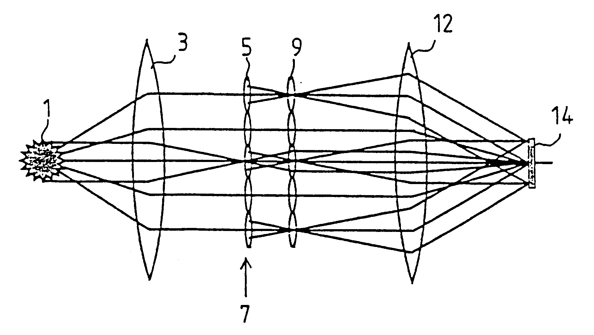
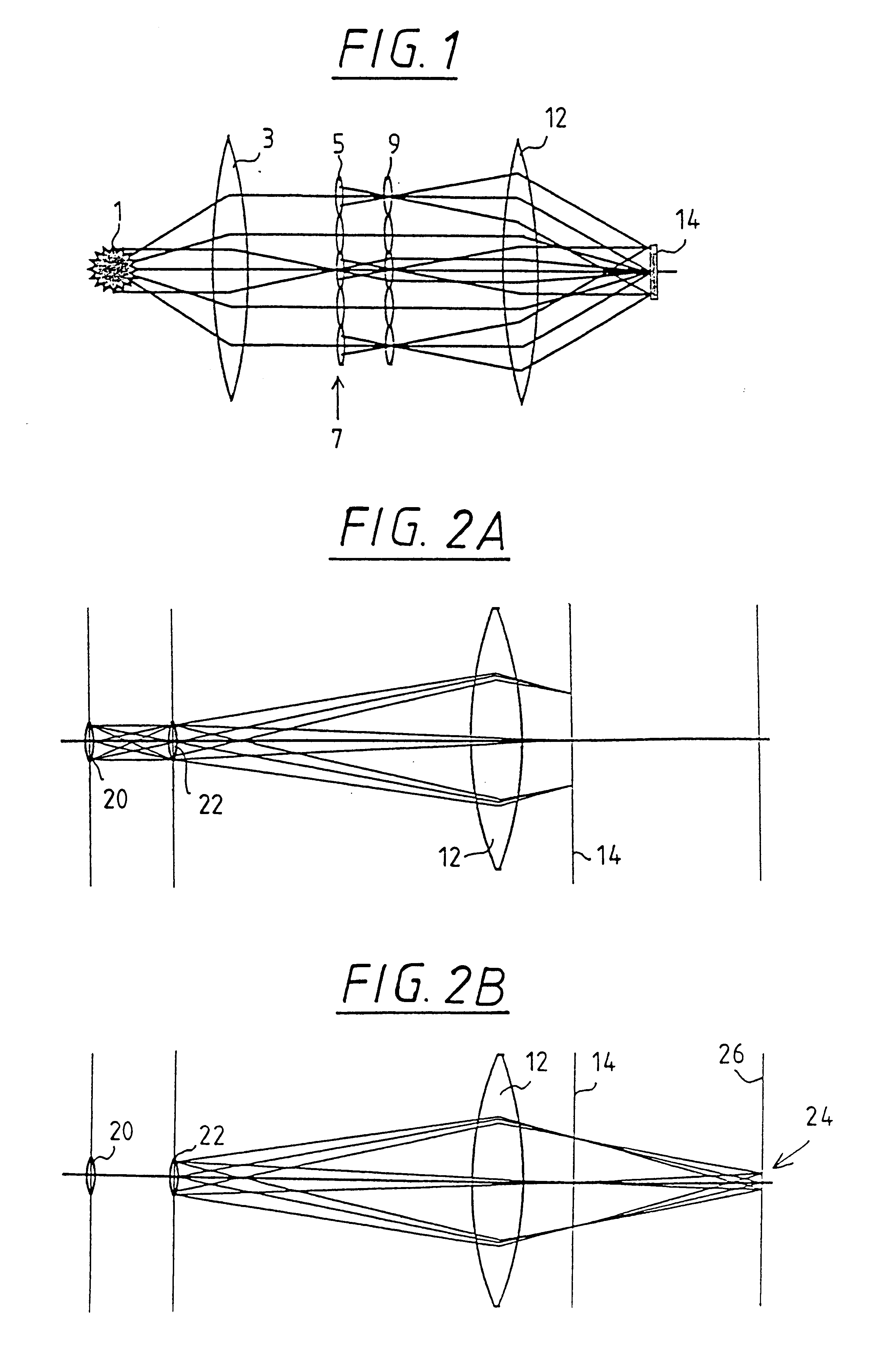
In FIG. 1, a principle diagram of the beam path of a system with two honeycomb plates is illustrated. The light of source 1 is collected by means of a collector lens 3 and converted into a parallel or convergent pencil beam. The field honeycombs 5 of the first honeycomb plate 7 decompose the light pencil and produce secondary light sources at the site of the pupil honeycombs 9. The field lens 12 forms these secondary sources in the exit pupil of the illumination system or the entrance pupil of the subsequent objective. Such an arrangement is characterized by an interlinked beam path of field and pupil planes from the source up to the entrance pup...


PUM

PropertyMeasurementUnit
wavelengthsaaaaaaaaaa
distanceaaaaaaaaaa
wavelengthsaaaaaaaaaa

Abstract

The invention concerns an illumination system for wavelengths <=193 nm, particularly for EUV lithography, with at least one light source, which has an illumination A in a predetermined surface; at least one device for producing secondary light sources; at least one mirror or lens device comprising at least one mirror or one lens, which is or are organized into raster elements; one or more optical elements, which are arranged between the mirror or lens device comprising at least one mirror or one lens, which is or are organized into raster elements and the reticle plane, whereby the optical elements image the secondary light sources in the exit pupil of the illumination system.The illumination system is characterized by the fact that the raster elements of the one or more mirror or lenses are shaped and arranged in such a way that the images of the raster elements cover by means of the optical elements the major portion of the reticle plane and that the exit pupil defined by aperture and filling degree is illuminated.

Description

1. Field of the InventionThe invention concerns an illumination system according to the preamble of claim I as well as a projection exposure unit with such an illumination system.In order to be able to further reduce the structural widths of electronic components, particularly in the submicron range, it is necessary to reduce the wavelengths of the light utilized for microlithography. Lithography with soft x-ray radiation, so-called EUV (extreme UV) lithography, is conceivable at wavelengths smaller than 193 nm, for example.2. Description of the Prior ArtAn illumination system suitable for EUV lithography will illuminate with as few reflections as possible the field provided for EUV lithography, particularly the annular field of an objective in a homogeneous manner, i.e., uniformly; further, the aperture diaphragm or pupil of the objective will be illuminated independent of field up to a specific filling ratio .sigma. and the exit pupil of the illumination system will lie in the ent...

Claims


Application Information

Patent Timeline
Patent Type & Authority Patents(United States)
IPC IPC(8): G03F7/20G21K5/00G21K1/06G21K1/00F21V5/00F21V7/00F21V13/04G21K5/02H01L21/027
CPCB82Y10/00G02B27/0905G02B27/0961G02B27/0983G03F7/70083G03F7/70108G03F7/70166G03F7/702G03F7/70233G03F7/70358G03F7/708G21K1/06G21K2201/06
Inventor SCHULTZ, JORGWANGLER, JOHANNESSCHUSTER, KARL-HEINZDINGER, UDO
Owner CARL ZEISS SMT GMBH
Why Eureka
Try Eureka