LED lighting system

a technology of led lighting and diodes, which is applied in the direction of lighting and heating apparatus, semiconductor devices for light sources, transportation and packaging, etc., can solve the problems of shortening the life, being impractical in conventional lighting devices, and only reducing the thermal resistance to a certain extent, so as to reduce heat resistance and improve heat dissipation

Inactive Publication Date: 2006-08-31
ATEX CO LTD
View PDF3 Cites 283 Cited by
  • Summary
  • Abstract
  • Description
  • Claims
  • Application Information

AI Technical Summary

Benefits of technology

[0027] As the flexible printed circuit board is attached to the light sourse fixing member with a thermal-conductive adhesive, the LEDs can be firmly fixed on the light source fixing member, thereby reducing heat resistance and improving heat dissipation.

Problems solved by technology

Insufficient heat dissipation considerably shortens the life and leads to failure.
To lower the junction temperature Tj, it is necessary to lower one of the ambient temperature Ta, the thermal resistance Rja and the applied power W. In order to lower the ambient temperature Ta, a cooling fan or the like can be used for air-cooling, which is, however, impractical in conventional lighting devices.
However, due to the small contacting area between the metal substrate and the bugle-shaped metal heat radiation part, the thermal resistance can only be reduced to a certain extent.
Since the substrate on which the LEDs are mounted is also curved, the mounting steps are complicated.

Method used


Image

  • LED lighting system
  • LED lighting system
  • LED lighting system

Examples


embodiment 1

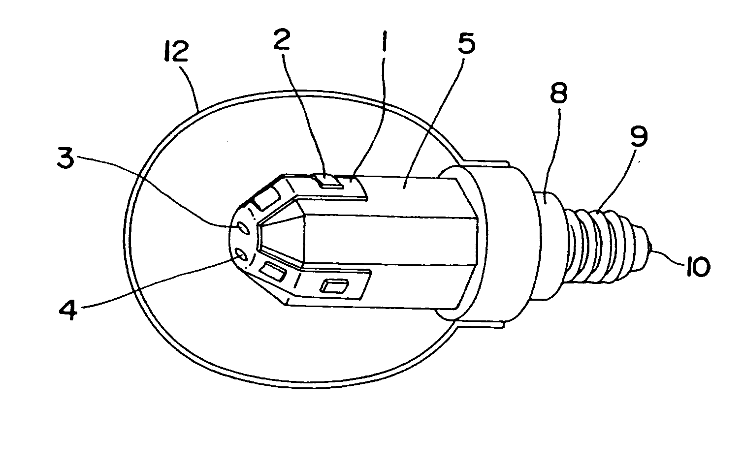
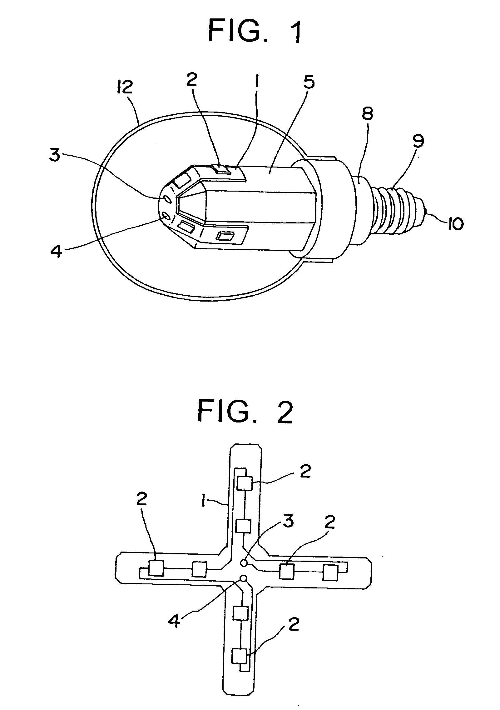
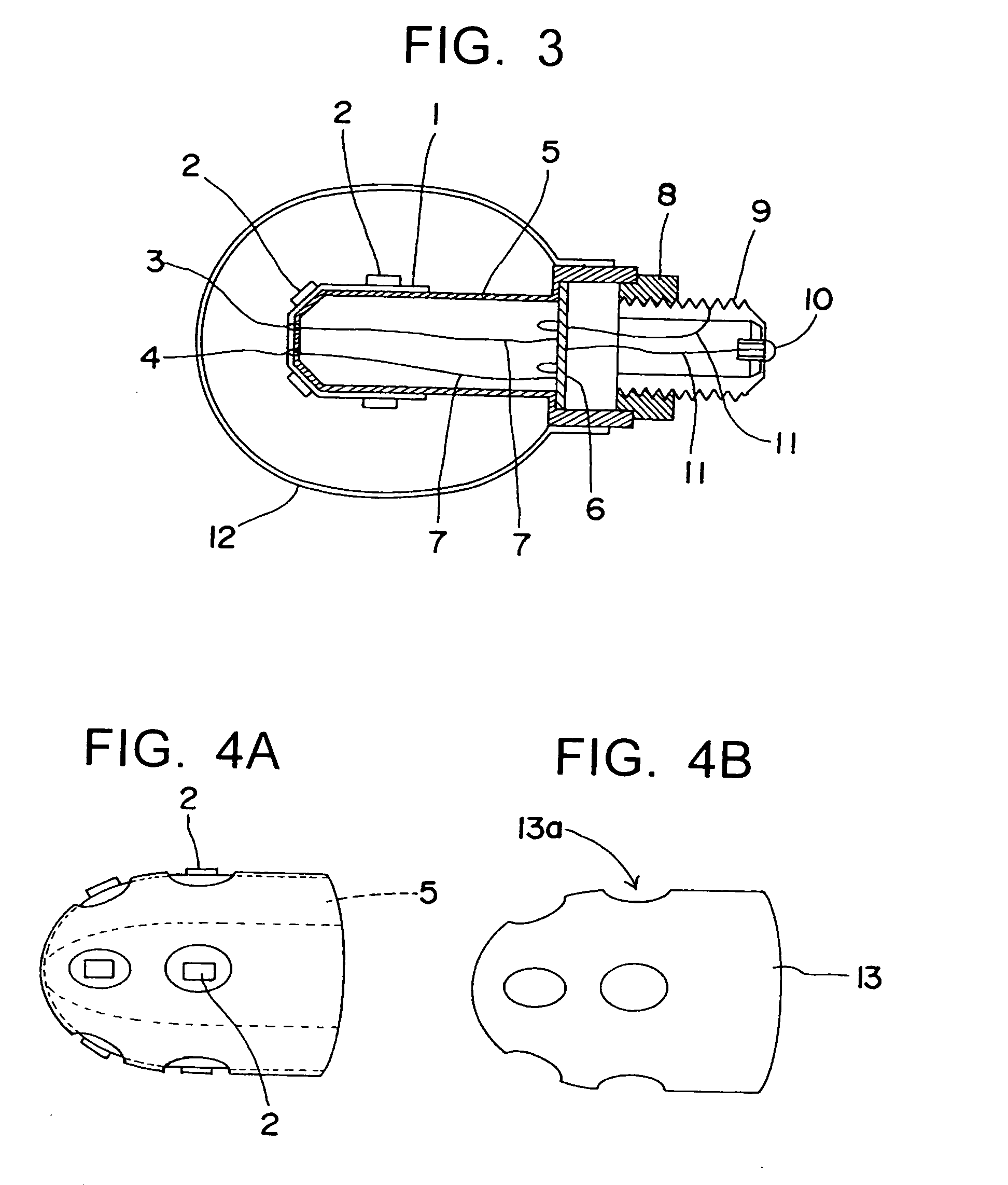
[0038]FIG. 1 is a perspective view illustrating a structure of an LED lighting system according to a first embodiment of the present invention; FIG. 2 is a plan view of a flexible printed circuit board according to the first embodiment of the present invention; and FIG. 3 is a sectional view of the LED lighting system according to the first embodiment of the present invention.

[0039] In the LED lighting system of the first embodiment, as shown in FIG. 2, a plurality of LEDs 2 are mounted on a flexible printed circuit board (referred to as “FPC” hereinafter) 1 which has a radial shape and can be flat when developed. The LEDs 2 are connected by printed wiring with serial connection to each other, for example, and linked to terminals 3 and 4. As the FPC 1, a thin epoxy substrate or the like can be employed. In the present embodiment, the FPC 1 is attached on a surface of a core 5 made of aluminum and having an outer shape of an octagonal prism using a heat-conductive adhesive such as a...

embodiment 2

[0044]FIG. 5 is a perspective view illustrating a structure of an LED lighting system according to a second embodiment of the present invention; FIG. 6 is a front view thereof; and FIG. 7 is a sectional view of the same.

[0045] According to the lighting system of the second embodiment, a plurality of LEDs 22 are mounted on an FPC 21 which has a radial shape and can be flat when developed. The LEDs 22 are connected by printed wiring with serial connection to each other, for example, and linked to terminals 23 and 24. As the FPC 21, a thin epoxy substrate or the like can be employed. The FPC 21 is attached on an inner surface of a reflector 25 made of aluminum using a heat-conductive adhesive such as a thermal-conductive silicon resin, for example. To a base end of the reflector 25, a cylindrical member 26 which has holes 26a for heat dissipation is connected. Wires 27 which connect with the terminals 23 and 24 of the FPC 21 are drawn to an inside of the cylindrical member 26 to be co...


PUM


Abstract

Provided is an LED lighting system with a smaller heat resistance of the LED, which can be produced by simpler mounting steps and is capable of three-dimensionally arranging the LEDs depending on required directivity of each system. A plurality of LEDs 2 are mounted on an FPC 1 which has a radial shape and can be flat when developed. The LEDs 2 connected by printed wiring to each other and linked to terminals 3 and 4 are attached on a surface of a core 5 made of a material having a high thermal conductivity. Heat generated at a p-n junction of the LEDs 2 is transmitted to the core 5 via the FPC 1 and a thermal-conductive adhesive.

Description

BACKGROUND OF THE INVENTION [0001] 1. Field of the Invention [0002] The present invention relates to an LED (light emitting diode) lighting system using a plurality of LEDs, capable of emitting light with high luminance. [0003] 2. Description of the Related Art [0004] Since a white LED was commercialized, attempts to utilize an LED as a light source have been made. Compared to an electric bulb and a fluorescent lamp, an LED causes less power loss by thermal energy and has a longer life. Recently, white LEDs with high luminous intensity have been developed, and the application of an LED to a lighting system is becoming more realistic than the use of conventional light sources such as electric bulbs or fluorescent lamps. [0005] In order to obtain the same illuminance and color rendering properties as those of conventional electric bulbs and fluorescent lamps, it is necessary to provide a plurality of LED elements, which are similar to point sources, arranged on one face. [0006] Here, ...

Claims


Application Information

Patent Timeline
Patent Type & Authority Applications(United States)
IPC IPC(8): B60Q1/26
CPCF21K9/135F21V3/00F21Y2101/02F21Y2111/002F21Y2111/007F21V29/67F21K9/232F21Y2107/10F21Y2107/40F21Y2115/10
Inventor ISHIBASHI, KAZUO
Owner ATEX CO LTD
Why Eureka
Try Eureka