
Illumination systems utilizing highly reflective light emitting diodes and light recycling to enhance brightness

a light-emitting diode and illumination system technology, applied in the field of illumination systems and optical systems, can solve the problems of not being suitable for many applications such as illumination systems, and not being able to produce optical output images with luminances higher than the luminance of light sources

Inactive Publication Date: 2005-03-22
ZIMMERMAN SCOTT MOORE +1
View PDF6 Cites 184 Cited by
  • Summary
  • Abstract
  • Description
  • Claims
  • Application Information

AI Technical Summary

Benefits of technology

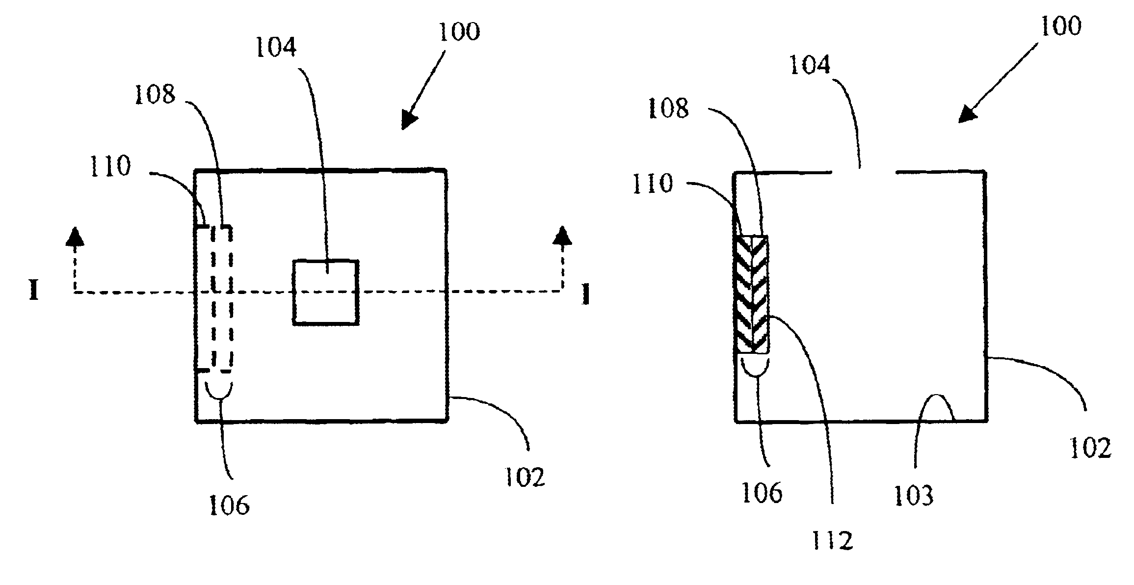
[0010]One embodiment of the present invention is an optical illumination system comprising: (a) a light source for generating light, wherein the light source is at least one light emitting diode having a reflecting surface with reflectivity RS greater than or equal to 50 percent, wherein the maximum intrinsic luminance of the light source is LI and wherein the total light emitting area of the light source is area AS; (b) a light-reflecting cavity enclosing the light source, wherein the inside surfaces of the light-reflecting cavity have reflectivity RC greater than or equal to 50 percent and wherein the inside surfaces of the light-reflecting cavity can reflect and recycle a portion of the light generated by the light source back to the light source; and (c) at least one light output aperture in the surface of the light-reflecting cavity, wherein the area of the light output aperture is area AO and wherein the area AO is less than the area AS. Under some conditions, it is possible to achieve an output luminance LO from the light output aperture that is greater than LI.
[0011]Another embodiment of the present invention is an optical illumination system comprising: (a) a light source for generating light, wherein the light source is at least one light emitting diode having a reflecting surface with reflectivity RS greater than or equal to 50 percent, wherein the maximum intrinsic luminance of the light source is LI and wherein the total light emitting area of the light source is area AS; (b) a light-reflecting cavity enclosing the light source, wherein the inside surfaces of the light-reflecting cavity have reflectivity RC greater than or equal to 50 percent and wherein the inside surfaces of the light-reflecting cavity can reflect and recycle a portion of the light generated by the light source back to the light source; (c) at least one light output aperture in the surface of the light-reflecting cavity, wherein the area of the light output aperture is area AO and wherein the area AO is less than the area AS; and (d) at least one partially reflecting optical element located in the light output optical path and located adjacent to the light output aperture of the light-reflecting cavity, wherein the partially reflecting optical element passes a first portion of the light transmitted by the light output aperture and reflects and recycles a second portion of the light transmitted by the light output aperture back into the light-reflecting cavity. Under some conditions, it is possible to achieve an output luminance LO from the light output aperture that is greater than LI.
[0012]Another embodiment of the present invention is an optical illumination system comprising: (a) a light source for generating light, wherein the light source is at least one light emitting diode having a reflecting surface with reflectivity RS greater than or equal to 50 percent, wherein the maximum intrinsic luminance of the light source is LI and wherein the total light emitting area of the light source is area AS; (b) a light-reflecting cavity enclosing the light source, wherein the inside surfaces of the light-reflecting cavity have reflectivity RC greater than or equal to 50 percent and wherein the inside surfaces of the light-reflecting cavity can reflect and recycle a portion of the light generated by the light source back to the light source; and (c) at least one light output aperture in the surface of the light-reflecting cavity, wherein the area of the light output aperture is area AO and wherein the area AO is less than the area AS; and (d) at least one light collimating element located in the light output optical path and located adjacent to the light output aperture of the light-reflecting cavity, wherein the light collimating element partially collimates the light passing through the light output aperture. Under some conditions, it is possible to achieve an output luminance LO from the light output aperture that is greater than LI.
[0013]Another embodiment of the present invention is an optical illumination system comprising: (a) a light source for generating light, wherein the light source is at least one light emitting diode having a reflecting surface with reflectivity RS greater than or equal to 50 percent, wherein the maximum intrinsic luminance of the light source is LI and wherein the total light emitting area of the light source is area AS; (b) a light-reflecting cavity enclosing the light source, wherein the inside surfaces of the light-reflecting cavity have reflectivity RC greater than or equal to 50 percent and wherein the inside surfaces of the light-reflecting cavity can reflect and recycle a portion of the light generated by the light source back to the light source; and (c) at least one light output aperture in the surface of the light-reflecting cavity, wherein the area of the light output aperture is area AO and wherein the area AO is less than the area AS; (d) at least one light collimating element located in the light output optical path and located adjacent to the light output aperture of the light-reflecting cavity, wherein the light collimating element partially collimates the light passing through the light output aperture; and (e) at least one partially reflecting optical element located in the light output optical path and located adjacent to the light collimating element, wherein the partially reflecting optical element passes a first portion of the light transmitted by the light output aperture and reflects and recycles a second portion of the light transmitted by the light output aperture back into the light-reflecting cavity. Under some conditions, it is possible to achieve an output luminance LO from the light output aperture that is greater than LI.
[0014]Another embodiment of the present invention is a first optical illumination system comprising: (a) a light source for generating light, wherein the light source is at least one light emitting diode having a reflecting surface with reflectivity RS greater than or equal to 50 percent, wherein the maximum intrinsic luminance of the light source is LI and wherein the total light emitting area of the light source is area AS; (b) a light-reflecting cavity enclosing the light source, wherein the inside surfaces of the light-reflecting cavity have reflectivity RC greater than or equal to 50 percent and wherein the inside surfaces of the light-reflecting cavity can reflect and recycle a portion of the light generated by the light source back to the light source; and (c) at least one light output aperture in the surface of the light-reflecting cavity, wherein the area of the light output aperture is area AO and wherein the area AO is less than the area AS; (d) at least one light collimating element located in the light output optical path and located adjacent to the light output aperture of the light-reflecting cavity, wherein the light collimating element partially collimates the light passing through the light output aperture; and (e) at least one partially reflecting optical element located in the light output optical path and located adjacent to the light collimating element, wherein the partially reflecting optical element passes a first portion of the light transmitted by the light output aperture and reflects and recycles a second portion of the light transmitted by the light output aperture into a second optical illumination system. Under some conditions, it is possible to achieve an output luminance LO from the light output aperture that is greater than LI.

Problems solved by technology

Light emitting diode (LED) sources are currently not used for projection television displays because LED sources do not have sufficient output luminance.
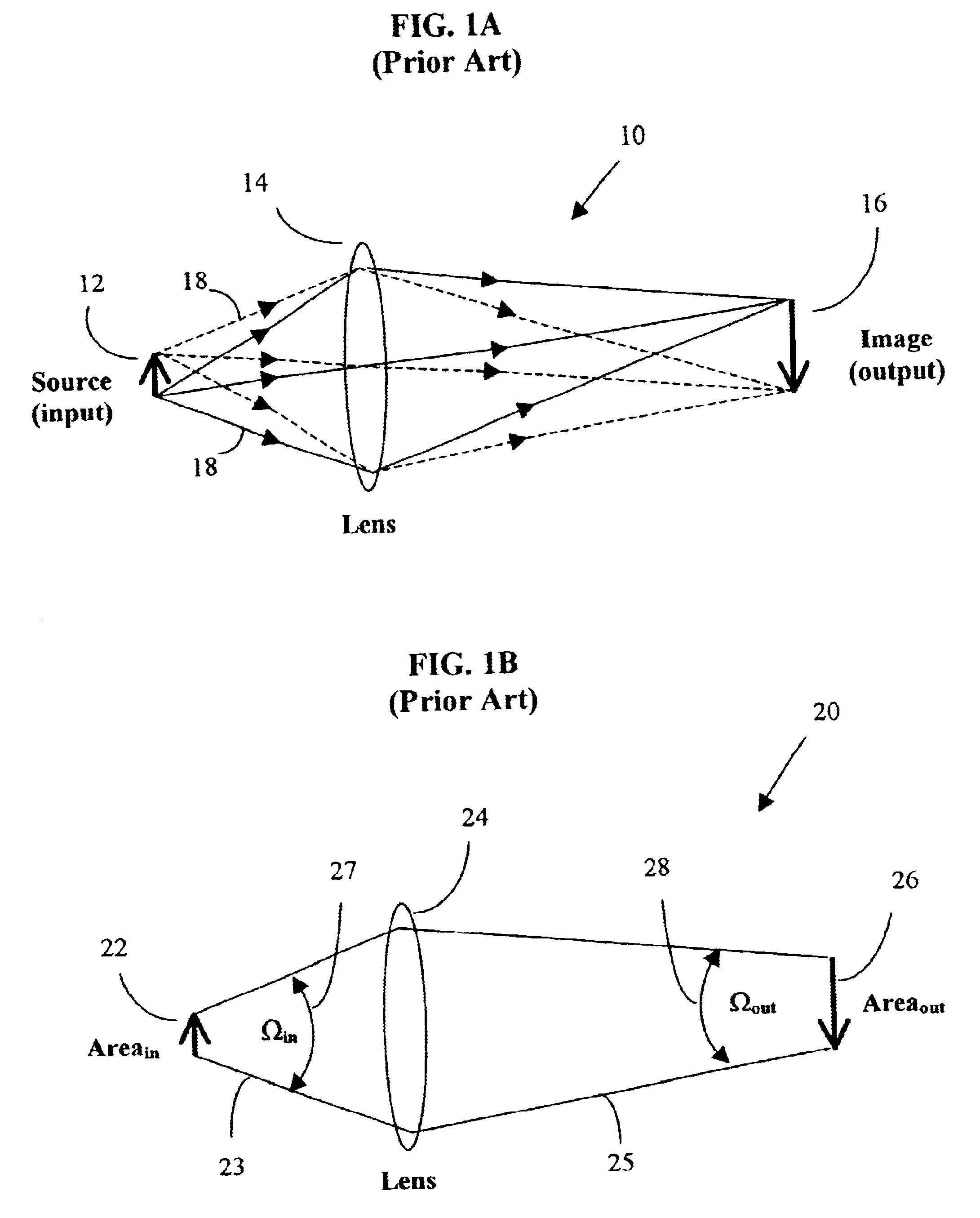
In a conventional optical system that transports light from an input source at one location to an output image at a second location, one cannot produce an optical output image that has a luminance higher than the luminance of the light source.
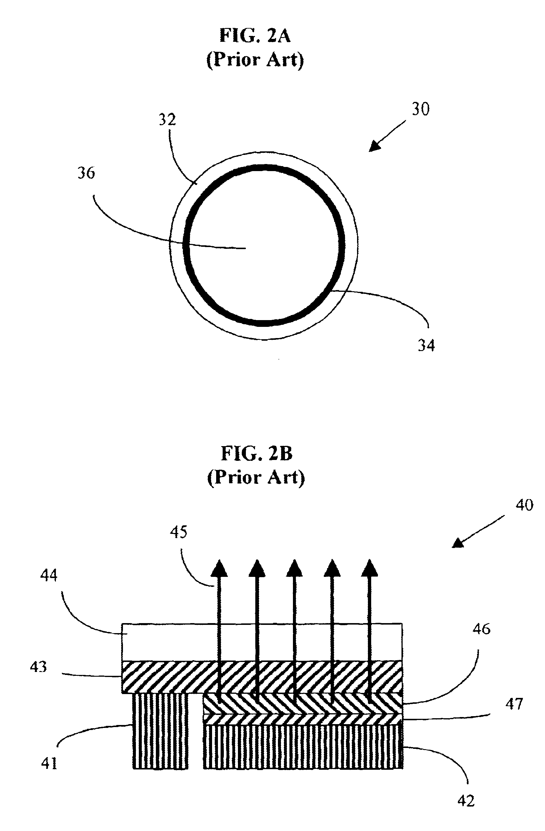
Such configurations, which typically use fluorescent lamps as light sources, are not suitable for many applications such as illumination systems for large projection displays.
Such an illumination system would be neither useful nor practical.
Typical prior LED designs placed one electrode on top of the device, which interfered with the light output from the top surface and resulted in devices with low reflectivity.
However, even the new green and blue gallium nitride LEDs do not have sufficient luminance for many applications such as large projection television displays.

Method used


Image

  • Illumination systems utilizing highly reflective light emitting diodes and light recycling to enhance brightness
  • Illumination systems utilizing highly reflective light emitting diodes and light recycling to enhance brightness
  • Illumination systems utilizing highly reflective light emitting diodes and light recycling to enhance brightness

Examples


example 1

[0056]In this example, a non-sequential, ray-tracing, computer program is used to calculate the relative output luminance and the overall output efficiency of a light-reflecting cavity containing twelve identical LED sources. Each LED source has dimensions of 2 mm×2 mm, an area of 4 mm2, an emitted flux of 150 lumens and intrinsic luminance LI. Each LED source is assumed to have a Lambertian output light distribution. The total area AS of the twelve LED sources is 48 mm2, and the total emitted flux of the twelve LED sources is 1800 lumens. The light-reflecting cavity has a square cross-section with inside dimensions of 2.8 mm×2.8 mm, inside length of 9 mm and a total inside area of 70.56 mm2. The total inside area includes the area of the twelve LED sources and the area of the output aperture. This example is illustrated schematically in FIG. 6. The light output aperture of the light-reflecting cavity has an area AO of 7.2 mm2 so that AO / AS=0.15, i.e. the area of the light output ap...

example 2

[0058]This EXAMPLE is similar to EXAMPLE 1 except that AO is reduced to 4.8 mm2 and the ratio AO / AS is thereby reduced to 0.10. In this example, a non-sequential, ray-tracing, computer program is used to calculate the relative output luminance and the overall output efficiency of a light-reflecting cavity containing twelve identical LED sources. For simplicity, the specular reflectivity RS of the LED sources is assumed to be identical in magnitude to the diffuse reflectivity RC of the inside surfaces of the light-reflecting cavity that are not covered by the LED sources. The results are shown below in TABLE 2.

TABLE 2Area AO ofTotal sourceSourceCavityLuminanceTotaloutput aperturearea ASArea ratioRSRCenhancementEfficiencylumens(mm2)(mm2)AO / AS(%)(%)(L0 / L1)(%)out (lm)4.8480.1040400.797.91424.8480.1050500.919.21664.8480.1060601.0810.81944.8480.1070701.3813.82484.8480.1080801.8919.23464.8480.1090903.1131.15604.8480.1098986.8768.71237

[0059]The computer modeling results indicate that for RS...

example 3

[0060]This EXAMPLE is similar to EXAMPLE 1 and EXAMPLE 2 except that AO is reduced to 2.4 mm2 and the ratio AO / AS is reduced to 0.05. In this example, a non-sequential, ray-tracing, computer program is used to calculate the relative output luminance and the overall output efficiency of a light-reflecting cavity containing twelve identical LED sources. For simplicity, the specular reflectivity RS of the LED sources is assumed to be identical in magnitude to the diffuse reflectivity RC of the inside surfaces of the light-reflecting cavity that are not covered by the sources. The results are shown below in TABLE 3.

TABLE 3Area AO ofTotal sourceSourceCavityLuminanceTotaloutput aperturearea ASArea ratioRSRCenhancementEfficiencylumens(mm2)(mm2)AO / AS(%)(%)(L0 / L1)(%)out (lm)2.4480.0540400.874.4792.4480.0550501.005.0902.4480.0560601.195.91062.4480.0570701.497.51352.4480.0580802.1210.61912.4480.0590903.6618.33292.4480.05989810.3451.7931

[0061]The computer modeling results indicate that for RS=R...


PUM


Abstract

An illumination system that has an output luminance (brightness) LO that is greater than the intrinsic output luminance (brightness) LI of the light emitting diodes used within the system. The system utilizes one or more light emitting diodes having highly reflective surfaces and recycles a portion of the light generated by the light emitting diodes back to the light emitting diodes in order to enhance the effective luminance. The illumination system includes a light-reflecting cavity and one or more highly reflective light emitting diodes having total surface area AS mounted inside the cavity, either on the interior surfaces of the cavity or within the cavity volume. The cavity has a light output aperture of area AO. The light emitting diodes have reflectivity RS. The exposed inside surfaces of the light-reflecting cavity have reflectivity RC. In order to achieve enhanced brightness, it is required that the area of the light output aperture AO be less than the total area AS of the light emitting diodes. It is preferred that reflectivity RC and reflectivity RS each be at least 50%, more preferably 75% and most preferably 90%. Illumination systems with enhanced luminance resulting from light recycling may be used in projection displays, flat-panel displays, avionics displays, automotive lighting, residential lighting, commercial lighting and industrial lighting applications.

Description

TECHNICAL FIELD[0002]This invention relates to illumination systems and optical systems incorporating illumination systems, including projection displays, flat-panel displays, avionics displays, automotive lighting, residential lighting, commercial lighting, industrial lighting and the like.BACKGROUND OF THE INVENTION[0003]Illumination systems are used as either stand-alone light sources or as internal light sources for more complex optical systems. Examples of optical systems that utilize or incorporate illumination systems include projection displays, flat-panel displays, avionics displays, automotive lighting, residential lighting, commercial lighting and industrial lighting applications.[0004]Many applications require illumination systems with high luminance (brightness) and a small effective emitting area. The term “luminance” or brightness is defined as lumens per unit area per unit solid angle. An example of a conventional light source with high luminance and a small effectiv...

Claims


Application Information

Patent Timeline
Patent Type & Authority Patents(United States)
IPC IPC(8): F21V9/06F21V9/14F21V9/00F21V7/00H01K1/26H01K1/00H01L33/00G02B17/06G02B19/00
CPCG02B17/0668G02B19/00Y10S362/80G02B19/0066G02B19/0019
Inventor ZIMMERMAN, SCOTT MOOREBEESON, KARL WAYNE
Owner ZIMMERMAN SCOTT MOORE
Learn More