Electrical connector

a technology of electrical connectors and connectors, applied in the direction of coupling device connections, incorrect coupling prevention, engagement/disengagement of coupling parts, etc., can solve the problems of reducing the working efficiency and ensuring a good plugging. , to achieve the effect of preventing the working efficiency of plugging and unplugging operation, reducing the maintaining strength of the lock

Inactive Publication Date: 2005-03-22
HIROSE ELECTRIC GROUP
View PDF5 Cites 41 Cited by
  • Summary
  • Abstract
  • Description
  • Claims
  • Application Information

AI Technical Summary

Benefits of technology

Accordingly, it is an object of the invention to provide an electrical connector, wherein the connector is not broken even when forcibly inserted or removed in any direction, thus securing firm operation, the friction wear of the metal upon the insertion and removal of the connector is controlled, thus preventing the reduction of the maintaining strength of the lock, and increasing the working efficiency of the plugging and unplugging operation.
With such structures, is provided an electrical connector, wherein even when forcible insertion or removal in any directions is attempted, the connectors are not broken, the firm operation is secured, the frictional wear of the connector members during the plugging and unplugging is controlled, the reduction of the maintaining strength of the lock is prevented, and the working efficiency of the plugging and unplugging operation is prevented.

Problems solved by technology

However, in such a conventional connector, since the engagement between the locking piece 6 and the engagement hole 7 is performed only on one side, if the connector 1 is inserted into the mating connector 2 in an inclined condition, even if it is a small inclination in any direction, it is difficult to secure a good plugging between the connectors 1 and 2.
Also, if forcibly inserted or removed, the connectors 1 and 2 may be broken, resulting in a malfunction.
Consequently, the locking piece 6 and the metal case 4 are scraped away by friction of the contact, which gradually reduces the maintaining strength of the lock.
Moreover, since the locking piece 6 projects outwardly, it may be hooked on clothes during the plugging and unplugging operation of the connectors, which reduces the working efficiency.

Method used


Image

  • Electrical connector
  • Electrical connector
  • Electrical connector

Examples


Embodiment Construction

Embodiments of the present invention will now be described with reference to the accompanying drawings.

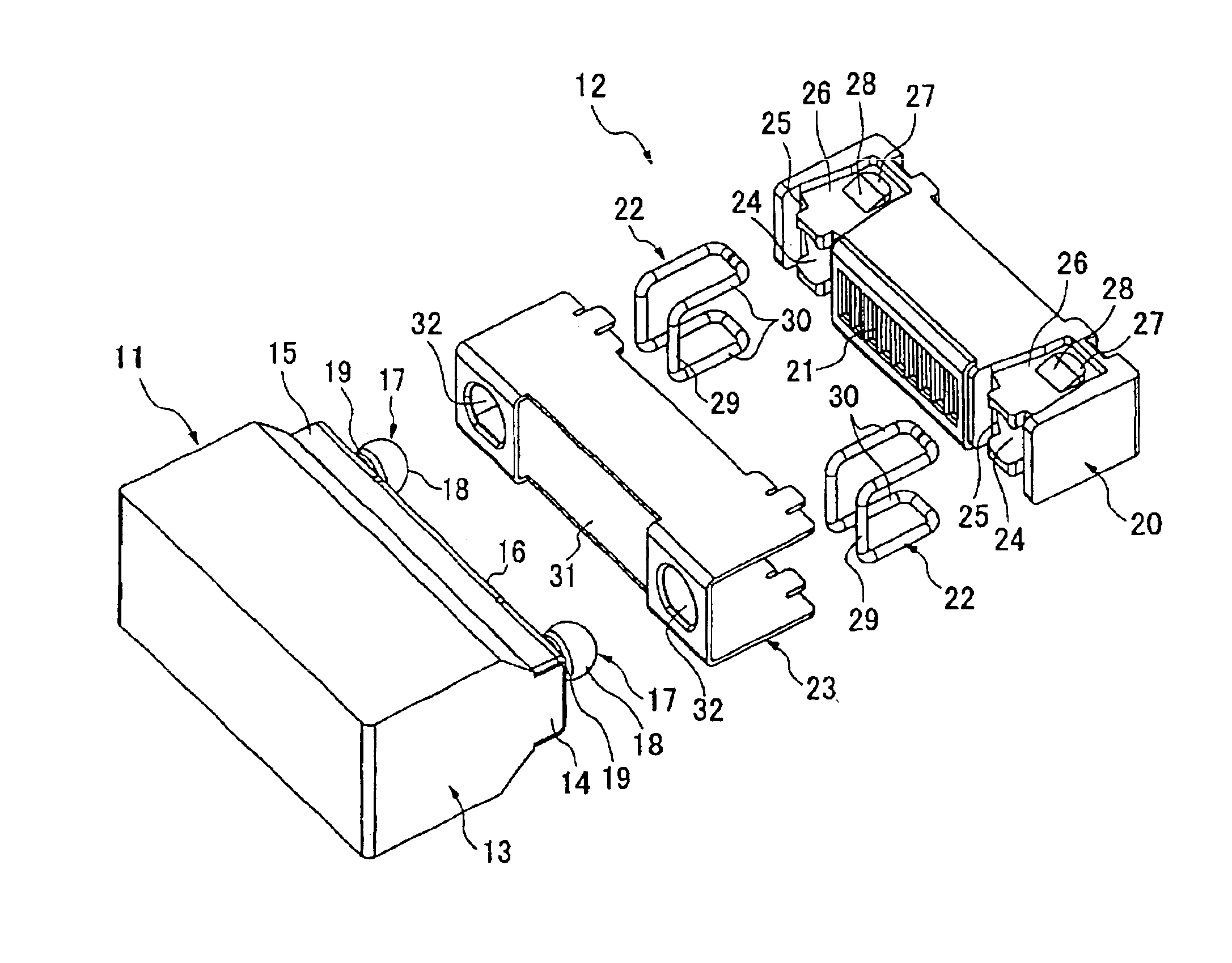
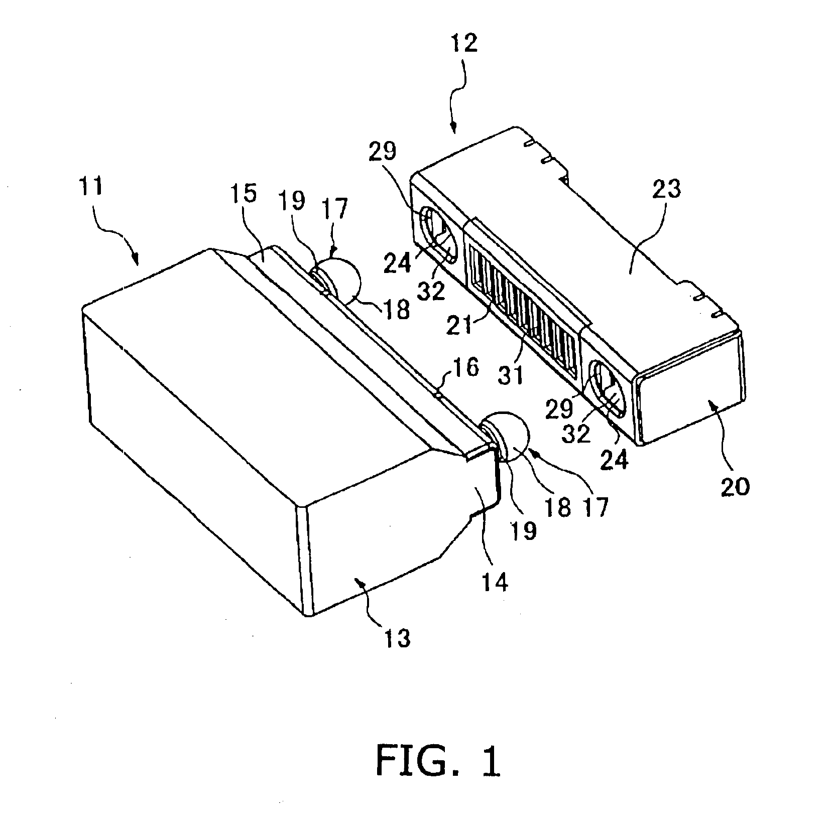
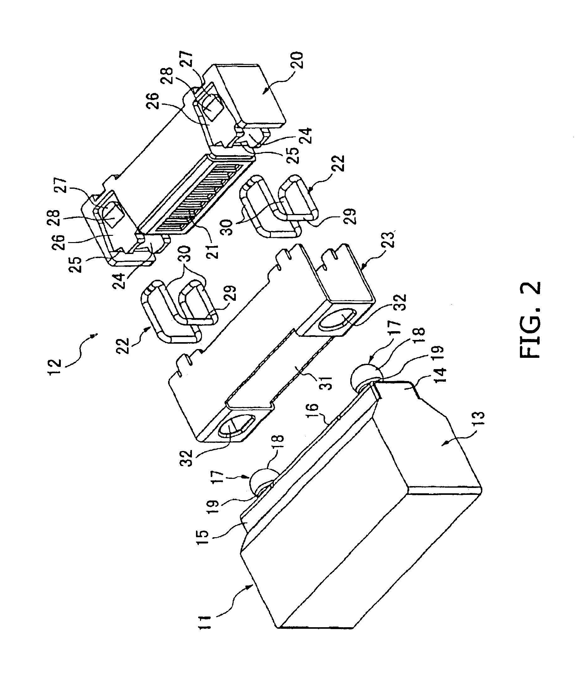
A connector 11 and a mating connector 12 are electrically connected to each other when the connector 11 is plugged into the mating connector 12.

In FIGS. 1-3, the connector 11 comprises an insulating housing 13 of a substantially rectangular parallelepiped which is long in a widthwise direction thereof, a plurality of contact elements 10 provided in a front end 14 of the insulating housing 13 in the widthwise direction of the housing 13, and a metal shell 15 covering the front end 14 of the insulating housing 13. The metal shell 15 is provided with a plugging face 16 for the contact elements 10 at a front face thereof. A pair of guide portions 17 projecting in a plugging direction of the connector 11 are provided at sides of the plugging face 16. Here, the guide portions 17 are provided at positions where no contact element is present, however, not always provided at sides of the co...


PUM


Abstract

An electrical connector (11) comprises an insulating housing (13), a plurality of contact elements (10) provided in a widthwise direction of the insulating housing, at least one guide portion 917) provided at a position where no contact element is present and guiding the connector to a position for plugging with a mating electrical connector (12), and a lock portion (18) provided at a top of the guide portion. The lock portion has a shape of a substantially sphere or a shape of a polyhedron having a top view of a substantially circle and locks a plugging condition between the electrical connectors.

Description

BACKGROUND OF THE INVENTION1. Field of the InventionThe present invention relates to an electrical connector, especially an electrical connector having a plurality of contact elements provided in a widthwise direction.2. Description of the Related ArtSome electrical connectors applicable for a portable telephone are provided with a plurality of contact elements provided in a widthwise direction and capable of locking and unlocking the plugging with a mating connector only by inserting and removing the connector into and from the mating connector in a plugging direction. Since they do not need a button and so forth, they are called a simple lock type. This type of connector is mostly used for application requiring frequent plugging and removing operations. In order to perform smooth plugging operation, as shown in FIG. 12, guide projections 3 are provided on sides of contact elements of a connector 1 and a cavity 5 is provided in a metal case 4 of a mating connector 2 to receive the ...

Claims


Application Information

Patent Timeline
Patent Type & Authority Patents(United States)
IPC IPC(8): H01R13/627H01R13/639H01R13/64
CPCH01R13/6276
Inventor SHIMIZU, SHINJITANAKA, MASAHIRO
Owner HIROSE ELECTRIC GROUP
Why Eureka
Try Eureka