
Safety device for blood collection

Inactive Publication Date: 2005-03-22
GREINER BIO ONE GMBH
View PDF14 Cites 87 Cited by
  • Summary
  • Abstract
  • Description
  • Claims
  • Application Information

AI Technical Summary

Benefits of technology

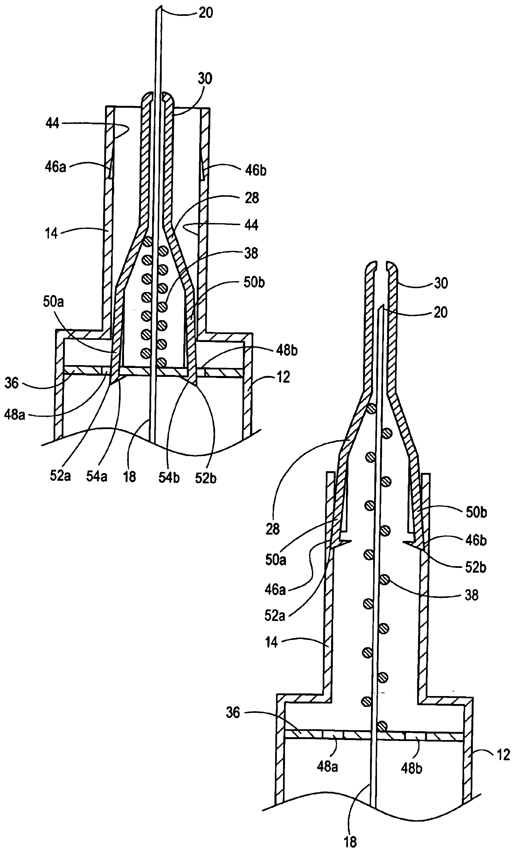
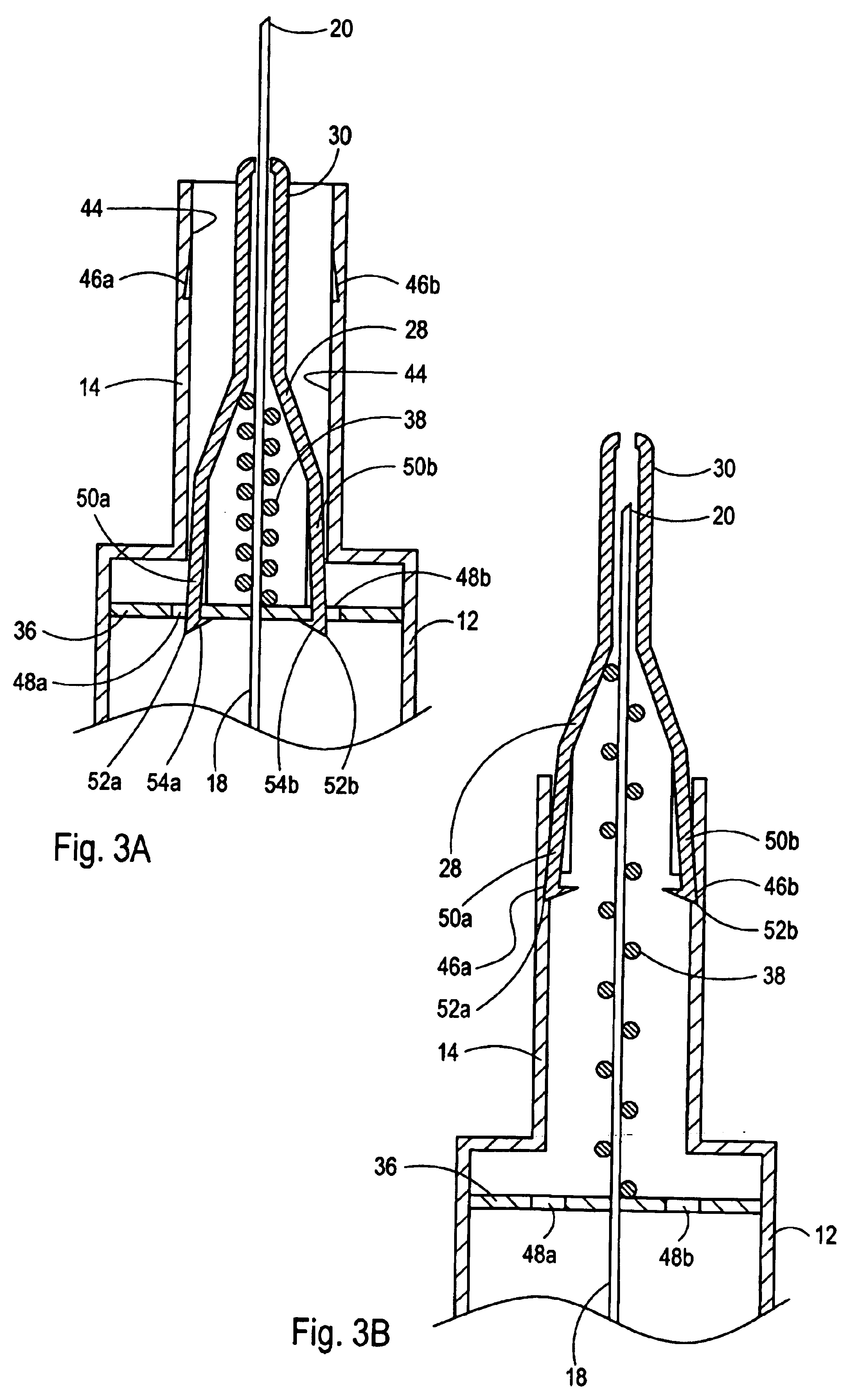
Once the guard member is in its distal position, the extension arms flex further away from the axis. This allows the points on the arms to engage with the indentation in the wall of the guideway. This engagement then prevents a subsequent movement of the guard member in the proximal direction. Importantly, when the guard member is in its distal position, with the extension arms engaged with respective indentations, the guard member completely covers the distal end of the needle and protects users against inadvertent or accidental “sticks”.
Another important aspect of the present invention is the interaction between the protuberances on the guard member that are inserted into the slots in the guideway. As the guard member moves from its proximal position to its distal position, this interaction prevents a rotation of the guard member about the axis relative to the device. Further, the dimensions of the slot are engineered so that the guard member has limited travel in the distal direction. Specifically, the distal ends of the slots act as stops for the protuberances on the guard member that prevent the spring from driving the guard member any further in a distal direction.

Problems solved by technology

Not surprisingly, this task requires a certain degree of skill.
After the procedure has been completed, however, this is not the case.

Method used


Image

  • Safety device for blood collection
  • Safety device for blood collection
  • Safety device for blood collection

Examples


Embodiment Construction

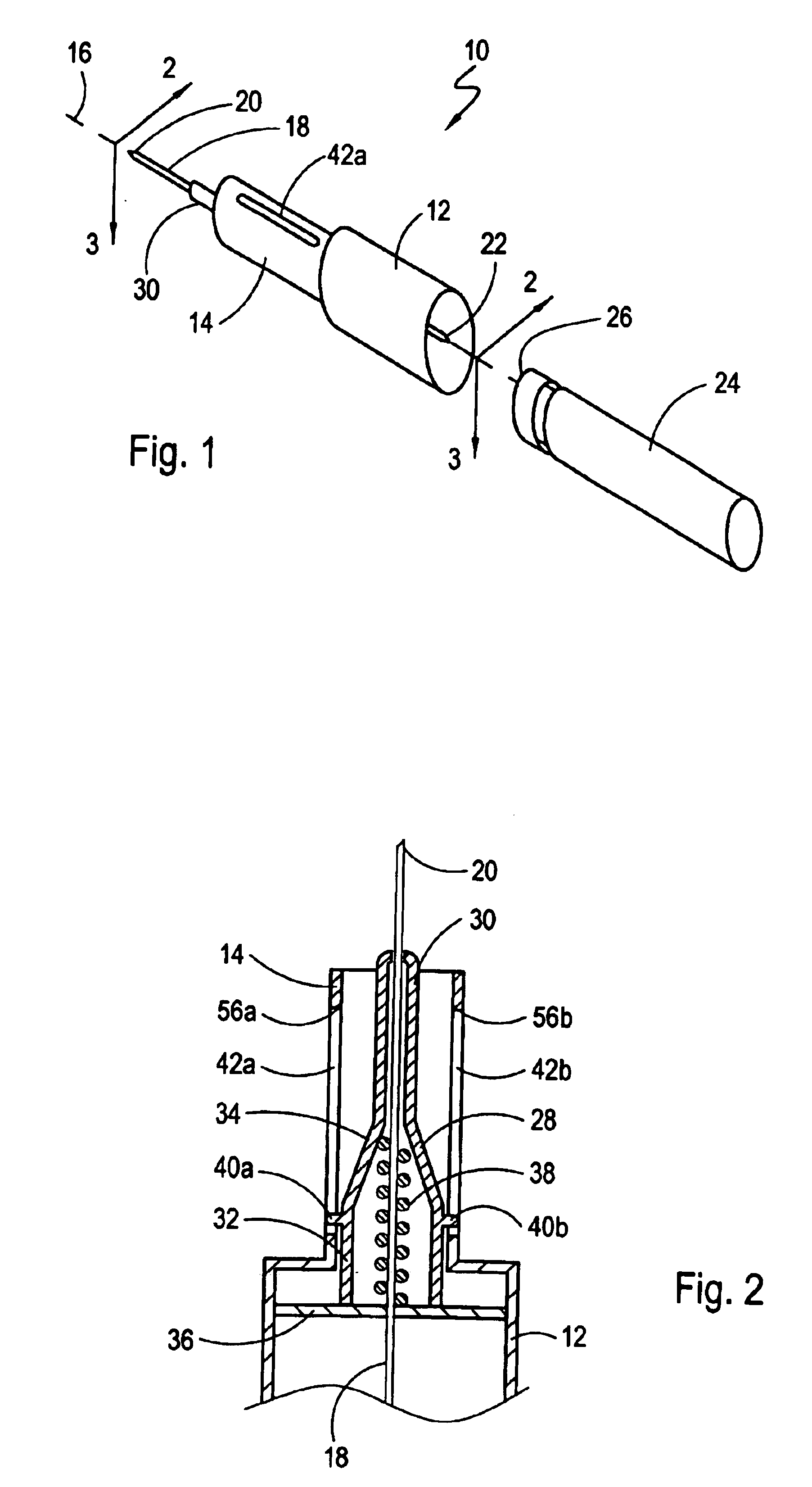
Referring initially to FIG. 1, a device in accordance with the present invention for use in a blood collection procedure is shown and generally designated 10. As shown, the device 10 includes a hollow, generally cylindrical shaped base member 12 and a hollow, generally cylindrical shaped guideway 14. Also, the base member 12 and guideway 14 are shown aligned coaxially along the axis 16, with the guideway 14 extending from the base member 12 in a distal direction. For reference purposes, the axis 16 shown in FIG. 1 is aligned with the respective longitudinal axes of the guideway 14 and the base member 12.

FIG. 1 also shows that the device 10 includes a substantially straight, hollow needle 18 that has both a distal tip 20 and a proximal tip 22. As shown, the needle 18 is aligned along the axis 16 with its proximal tip 22 positioned inside, and surrounded by, the base member 12. The distal tip 20, on the other hand, is shown extending from the device 10. This is done to facilitate inse...


PUM


Abstract

A safety device for protecting the needle of a blood collector includes a guard member that automatically covers the needle, after a blood collection procedure has been completed. Prior to the procedure, the guard member is restrained on the device in a proximal position to expose the needle, and to thereby facilitate the insertion of the needle into a vein of a patient. When a blood collection vial is engaged with the device, the guard member is released to move distally over the needle. Thus, after a procedure, and as the needle is being withdrawn from the patient, the guard member covers the needle to protect against subsequent inadvertent “sticks”.

Description

FIELD OF THE INVENTIONThe present invention pertains generally to devices and methods that are useful for collecting fluids. More particularly, the present invention pertains to devices and methods for collecting blood from a patient. The present invention is particularly, but not exclusively, useful for covering the needle of a blood collection device, to protect a user of the device against inadvertent or accidental “sticks,” after a blood collection procedure has been performed.BACKGROUND OF THE INVENTIONInadvertent or accidental needle “sticks” are to be generally avoided in any situation. This is particularly so, however, for situations such as in clinical environments where needles are used for specific medical purposes, such as for the collection of blood. In such situations, the risk that contaminated body fluids (e.g. blood) may be transferred from one individual to another by a needle “stick,” makes the prevention of such incidents extremely important.In general, a typical...

Claims


Application Information

Patent Timeline
IPC IPC(8): A61B5/15A61M5/32
CPCA61B5/1438A61M2005/3263A61M5/326A61B5/15003A61B5/150389A61B5/150473A61B5/150648A61B5/150732A61B5/154
Inventor ASBAGHI, HOOMAN A.
Owner GREINER BIO ONE GMBH
Learn More