Check patentability & draft patents in minutes with Patsnap Eureka AI!

Input impedance arrangement for RF transponder

a technology of input impedance and transponder, which is applied in the field of input impedance arrangement of rf transponder and transponder, can solve the problems of system not always performing satisfactorily, and the voltage recovery of rf transponders when not selected may not be adequate in some applications

Inactive Publication Date: 2005-03-22
ZEBRA TECH CORP
View PDF10 Cites 32 Cited by
  • Summary
  • Abstract
  • Description
  • Claims
  • Application Information

AI Technical Summary

Benefits of technology

Accordingly, it is an object of the present invention to provide a transponder, identification system and method with which the applicant believes the aforementioned disadvantages may at least be alleviated.

Problems solved by technology

In the known systems, the load impedance and antenna impedance are matched in known manner to yield optimum power transfer to the transponder circuitry, The applicant has found that especially in applications where the antenna apertures of a plurality of transponders overlap, these transponders are required to share the available energy and hence the transponders and the system do not always perform satisfactorily.
Furthermore, the voltage recovery of these transponders when not selected may not be adequate in some applications.

Method used


Image

  • Input impedance arrangement for RF transponder
  • Input impedance arrangement for RF transponder
  • Input impedance arrangement for RF transponder

Examples


Embodiment Construction

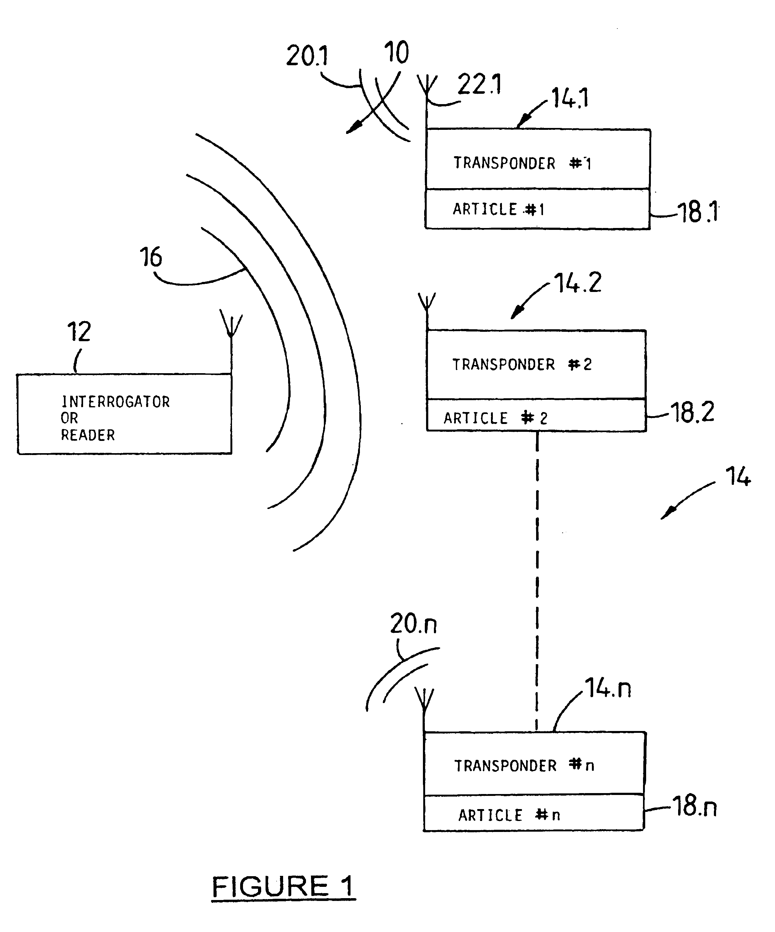
A known electronic radio frequency (RF) identification system is generally designed by the reference numeral 10 in FIG. 1.

The system 10 comprises a reader or interrogator 12 for transmitting an RF interrogation or energizing signal 16 towards a transponder population 14 comprising transponders 14.1 to 14.n. The transponders are of a kind deriving power from the energizing signal to power local circuits of the transponders. In use, the transponders are mounted on or associated with respective articles 18.1 to 18.n to be identified or counted.

Each transponder when energized as aforesaid, modulates the re-transmitted signal (for example by backscatter modulation of the energizing signal) to generate respective response signals 20.1 to 20.n comprising respective identification code data characteristic of that transponder. The reader 12 reads these response signals in sequential manner to identify the transponders and the articles, or simply to count the articles.

Referring to FIG. 2, kno...


PUM


Abstract

A transponder 14.1 for a radio frequency (RF) identification system comprises an antenna 22.1 having an antenna impedance (ZA) having a real part (RA) connected to transponder circuitry presenting a load impedance (ZL) having a real part (RL), a ratio (RLRA)of the real part (RL) of the load impedance and the real part (RA) of the antenna impedance having a first value that is bigger than one when the transponder is not transmitting data. During transmission of data the ratio is switched between the first value and a second smaller value.

Description

INTRODUCTION AND BACKGROUNDTHIS invention relates to electronic radio frequency (RF) identification systems. It more particularly relates to a transponder forming part of such a system, the system and associated methods of reading transponders and modulating an interrogation signal.Electronic RF identification systems are well known in the art. Such a system comprises an interrogator or reader and a plurality of transponders. In use, the reader transmits an RF interrogation signal towards the transponders. In some systems, the transponders derive power to energize load circuits from the interrogation or energizing signal, The transponders then generate respective response signals comprising respective identification code data unique to the transponder, by respectively backscatter modulating the energizing signal with the respective identification code data. The reader reads the response signals in sequential manner, thereby to identify and / or count the transponders and / or articles w...

Claims


Application Information

Patent Timeline
Patent Type & Authority Patents(United States)
IPC IPC(8): G06K19/07H01Q23/00H04B1/59H04B5/02
CPCG06K19/0723G06K19/0701
Inventor TURNER, CHRISTOPHER GORDON GERVASEMCMURRAY, JOHN
Owner ZEBRA TECH CORP
Features
  • R&D
  • Intellectual Property
  • Life Sciences
  • Materials
  • Tech Scout
  • Unparalleled Data Quality
  • Higher Quality Content
  • 60% Fewer Hallucinations
Learn More