Matching circuit for adaptive impedance matching in radio

Inactive Publication Date: 2011-02-17
SONY CORP +1
View PDF7 Cites 59 Cited by
  • Summary
  • Abstract
  • Description
  • Claims
  • Application Information

AI Technical Summary

Benefits of technology

The act of establishing plural configurations may be executed only when the receiver is not actively receiving a data call. Also, a calibration of a transmitter associated with the receiver may be established to account for an effect of th

Problems solved by technology

As understood herein, the impedance of the radio's antenna can be affected by the placement of

Method used


Image

  • Matching circuit for adaptive impedance matching in radio
  • Matching circuit for adaptive impedance matching in radio
  • Matching circuit for adaptive impedance matching in radio

Examples


Embodiment Construction

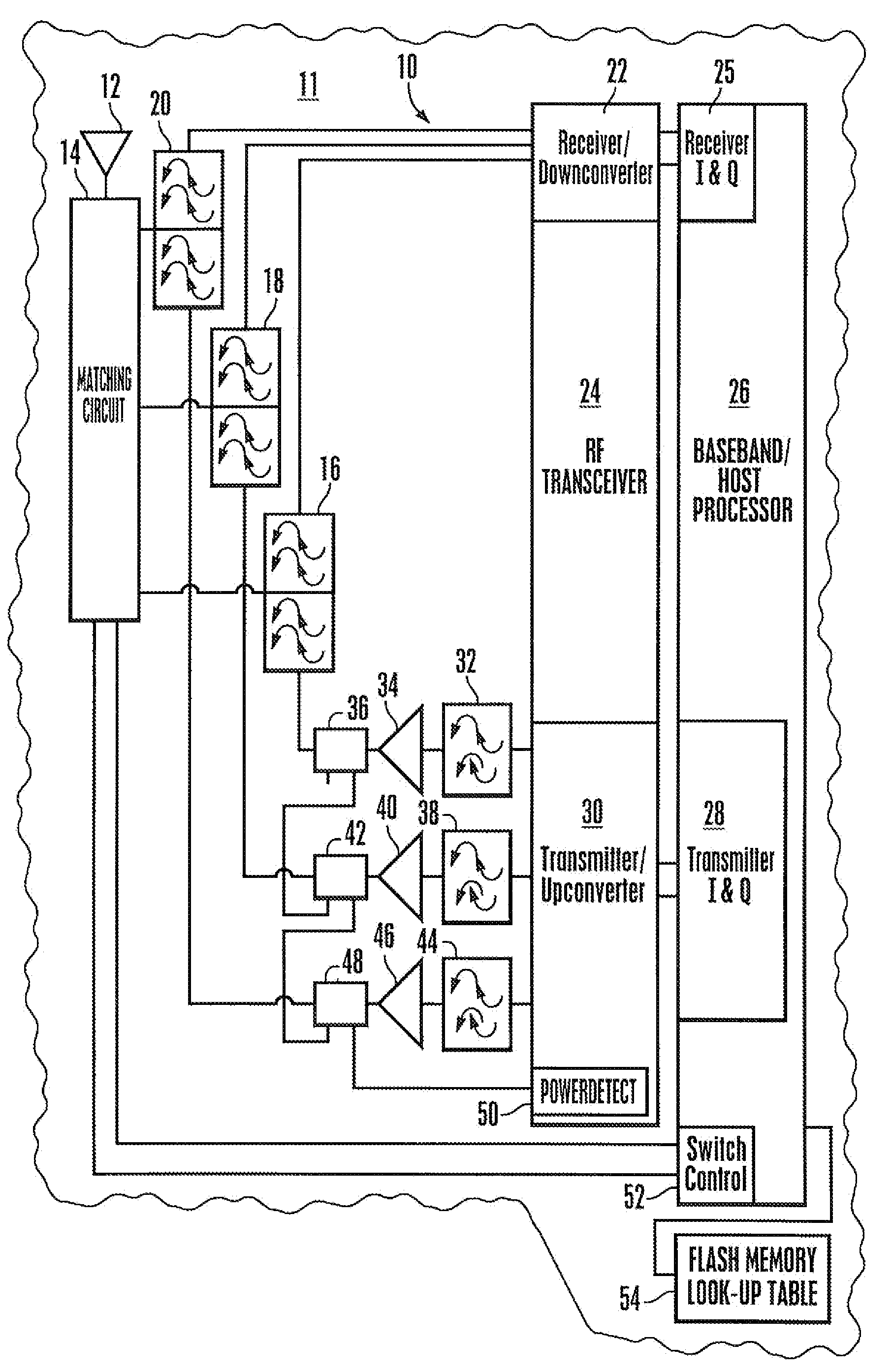
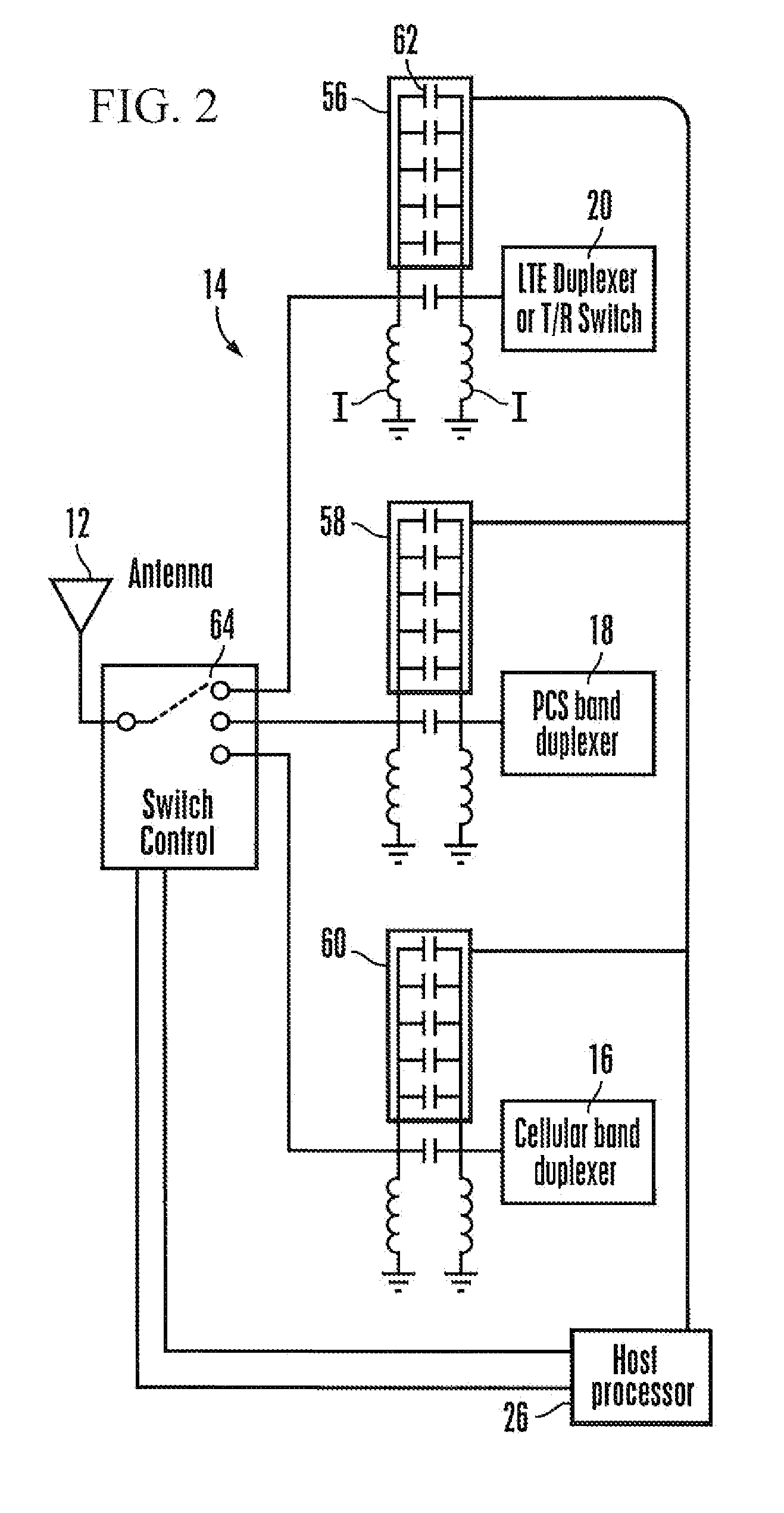
Referring initially to FIG. 1, a radio 10 that may be incorporated in a portable electronic device 11 such as a portable computer or wireless telephone includes an antenna 12 sending signals to and receiving signals from a matching circuit 14, an example of which is described further below in reference to FIG. 2. The matching circuit 14 may be connected to one or more filter-type components such as duplexers. In the example shown the matching circuit 14 communicates with a cellular duplexer 16, a personal communication service (PCS) duplexer 18, and a long-term evolution (LTE) duplexer or transmit / receiver (T / R) switch 20.

In turn, each of the components 16-20 communicates with a receiver / downconverter 22 of a radiofrequency (RF) transceiver 24. The receiver / downconverter converts signals in the RF domain to intermediate frequency (IF), which is sent to a receiver I&Q demodulator 25 of a host processor 26 for demodulation of the IF to baseband, which is processed by the host processo...


PUM


Abstract

An impedance matching circuit for a radio receives antenna signals and has its matching elements, such as capacitors, progressively switched into the circuit, with the matching element configuration resulting in the highest RSSI being subsequently used until a succeeding test or antenna impedance change. The effect of the matching circuit is accounted for in the transmitter calibration routine so that the matching circuit works for both half duplex and full duplex.

Description

FIELD OF THE INVENTIONThe present invention relates generally to circuits for adaptively matching impedance in a radio.BACKGROUND OF THE INVENTIONRadios are commonly used in wireless notebooks, wireless consumer electronics devices such as mobile telephones, etc. to provide wireless connectivity to a network. As understood herein, the impedance of the radio's antenna can be affected by the placement of a user's hand on the device and by other nearby objects, which can degrade radio performance.As further understood herein, not only would it be advantageous to address the problem noted above but to do so in a way that works not only in a half-duplex mode, in which transmitter performance is not necessarily affected by a change in antenna receiver-side impedance, but in a full-duplex mode as well, in which the transmitter performance typically is affected as antenna impedance changes.SUMMARY OF THE INVENTIONA system has a transceiver communicating with an antenna and a matching networ...

Claims


Application Information

Patent Timeline
IPC IPC(8): H04B1/44
CPCH03H7/40H04B1/52H04B1/0458
Inventor NGUYEN, HIENPARPIA, VIJAYZHOU, YI
Owner SONY CORP
Why Eureka
Try Eureka