Auto-tuned RFID reader antenna

a technology of radio frequency identification and auto-tuned circuit, which is applied in the direction of mechanical actuation of burglar alarms, hand-held items removal, instruments, etc., can solve the problems of reducing the range of readers, detuning the resonant circuit from the predetermined frequency, and affecting the accuracy of the reader

a technology of radio frequency identification and auto-tuned circuit, which is applied in the direction of mechanical actuation of burglar alarms, hand-held items removal, instruments, etc., can solve the problems of reducing the range of readers, detuning the resonant circuit from the predetermined frequency, and affecting the accuracy of the reader

US20070222605A1Active Publication Date: 2007-09-27ASSA ABLOY AB

Image

  • Auto-tuned RFID reader antenna
  • Auto-tuned RFID reader antenna
  • Auto-tuned RFID reader antenna

Examples


Embodiment Construction

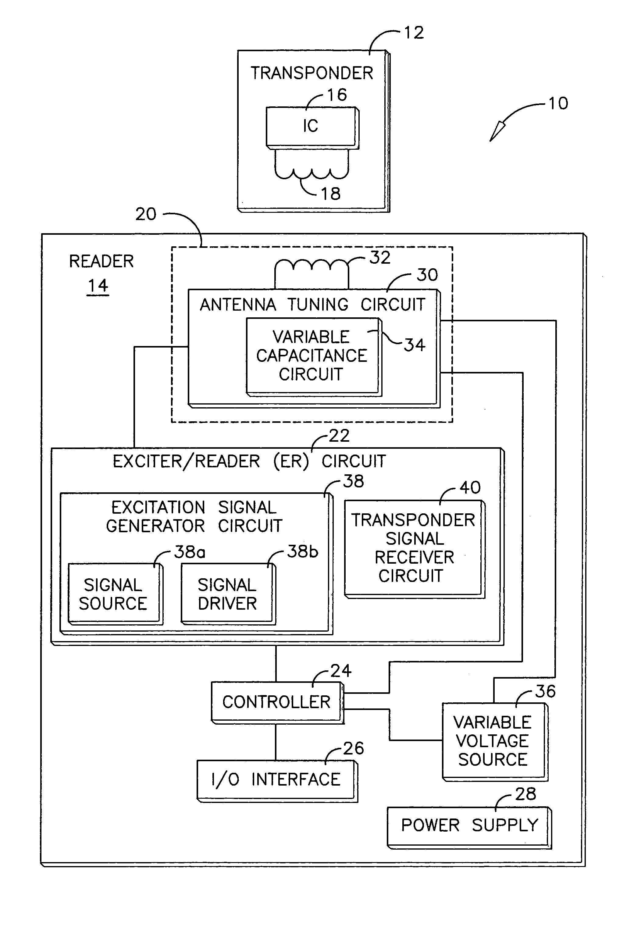
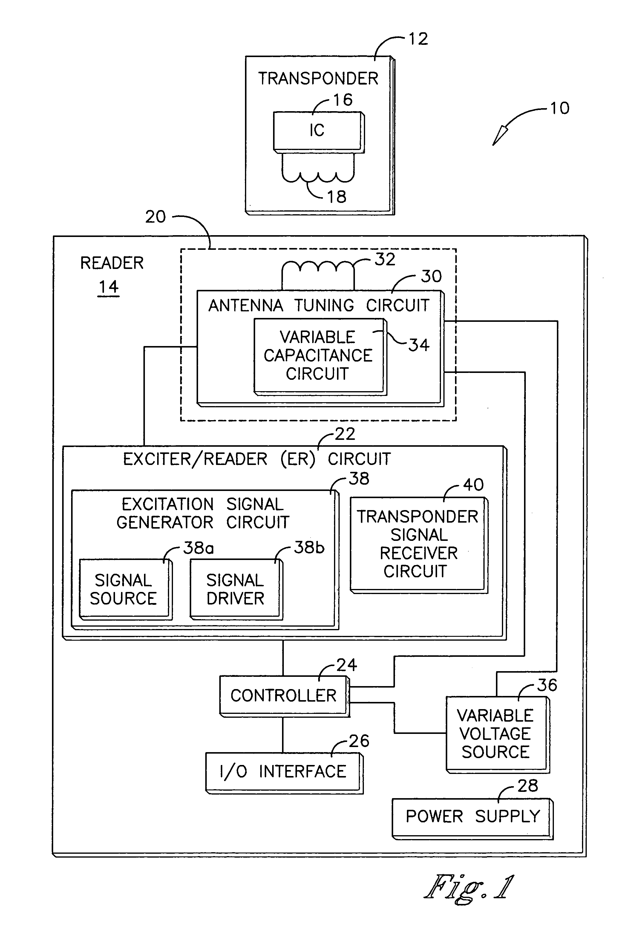
[0026] An RFID system is shown in FIG. 1 and generally designated 10. The RFID system 10 comprises a transponder 12 and a reader 14. The transponder 12 is preferably a passive transponder which does not require an internal power supply. The electrical power required to operate the passive transponder 12 is supplied to the transponder 12 by electromagnetic energy transmitted from the reader 14, which is of a specific frequency and a sufficient strength to power up the transponder 12.

[0027] The transponder 12 comprises a number of functional elements including a transponder integrated circuit (IC) 16 and a transponder antenna 18. The transponder IC 16 embodies the processing and memory capabilities of the transponder 12. The transponder antenna 18 is coupled to the transponder IC 16 and is preferably a conventional coil termed a “dual-function antenna” which performs both the receiving and transmitting functions of the transponder 12. Alternatively, two separate receiving and transmi...


PUM


Abstract

A reader for an RFID system includes an antenna assembly, a signal driver and a controller. The antenna assembly has an antenna coupled to an antenna tuning circuit which includes a variable capacitance circuit. The signal driver is coupled to the antenna assembly to apply a drive signal to the antenna assembly. The controller is coupled to the antenna assembly to determine a difference between an antenna impedance and a signal driver impedance and to set the variable capacitance at a set capacitance value which reduces the impedance difference.

Description

TECHNICAL FIELD [0001] The present invention relates generally to readers for radio frequency identification systems, more particularly, to an auto-tuning circuit for use with an antenna of a reader. BACKGROUND OF THE INVENTION [0002] Radio frequency identification (RFID) systems typically include at least one reader and a plurality of transponders, which are commonly termed credentials, cards, tags, or the like. The transponder may be an active or passive radio frequency communication device which is directly attached to or embedded in an article to be identified or otherwise characterized by the reader. Alternatively, the transponder may be embedded in a portable substrate, such as a card or tag, carried by a person or an article to be identified or otherwise characterized by the reader. An active transponder is powered up by its own internal power supply, such as a battery, which provides the operating power for the transponder circuitry. In contrast, a passive transponder is cha...

Claims


Application Information

Patent Timeline
27 Sep 2007
Publication
US20070222605A1
IPC
G08B13/14
CPC
G06K7/10316; G06K7/0008
Inventors
ANDRESKY, DAVID