
Tunable RFID tag for global applications

a global application and tag technology, applied in the field of tag containing an rfid transponder, can solve the problems of not being accepted, and not being able to meet the requirements of a single global standard for uhf communication

Inactive Publication Date: 2008-01-29
INTERMEC IP
View PDF8 Cites 57 Cited by
  • Summary
  • Abstract
  • Description
  • Claims
  • Application Information

AI Technical Summary

Benefits of technology

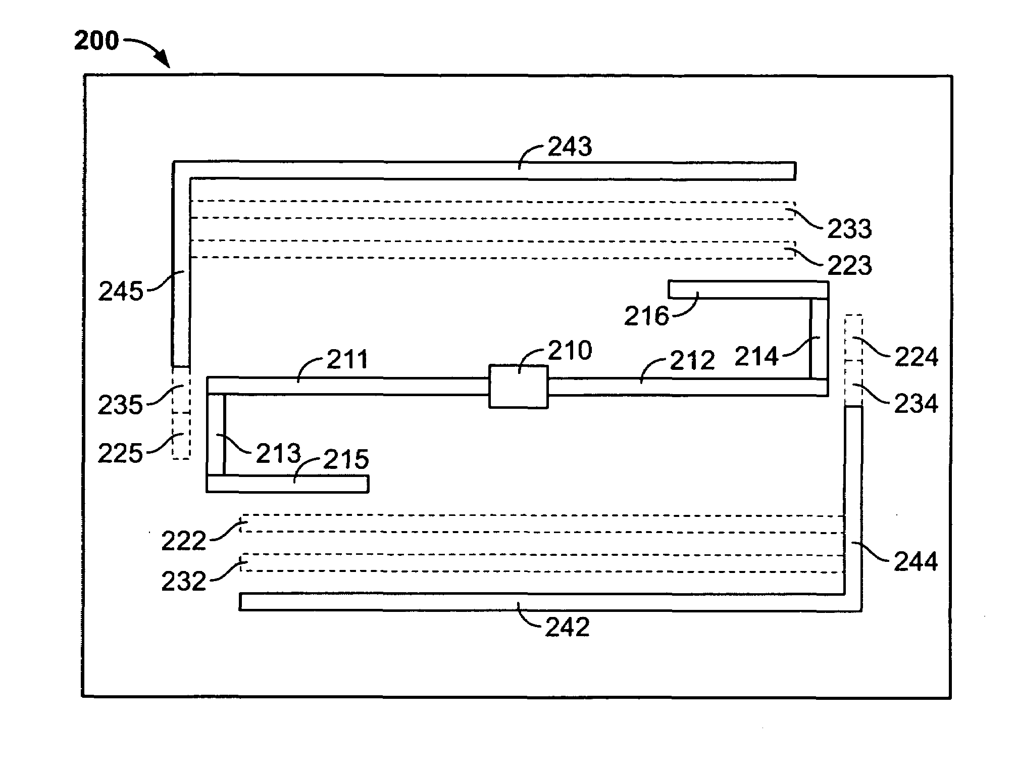
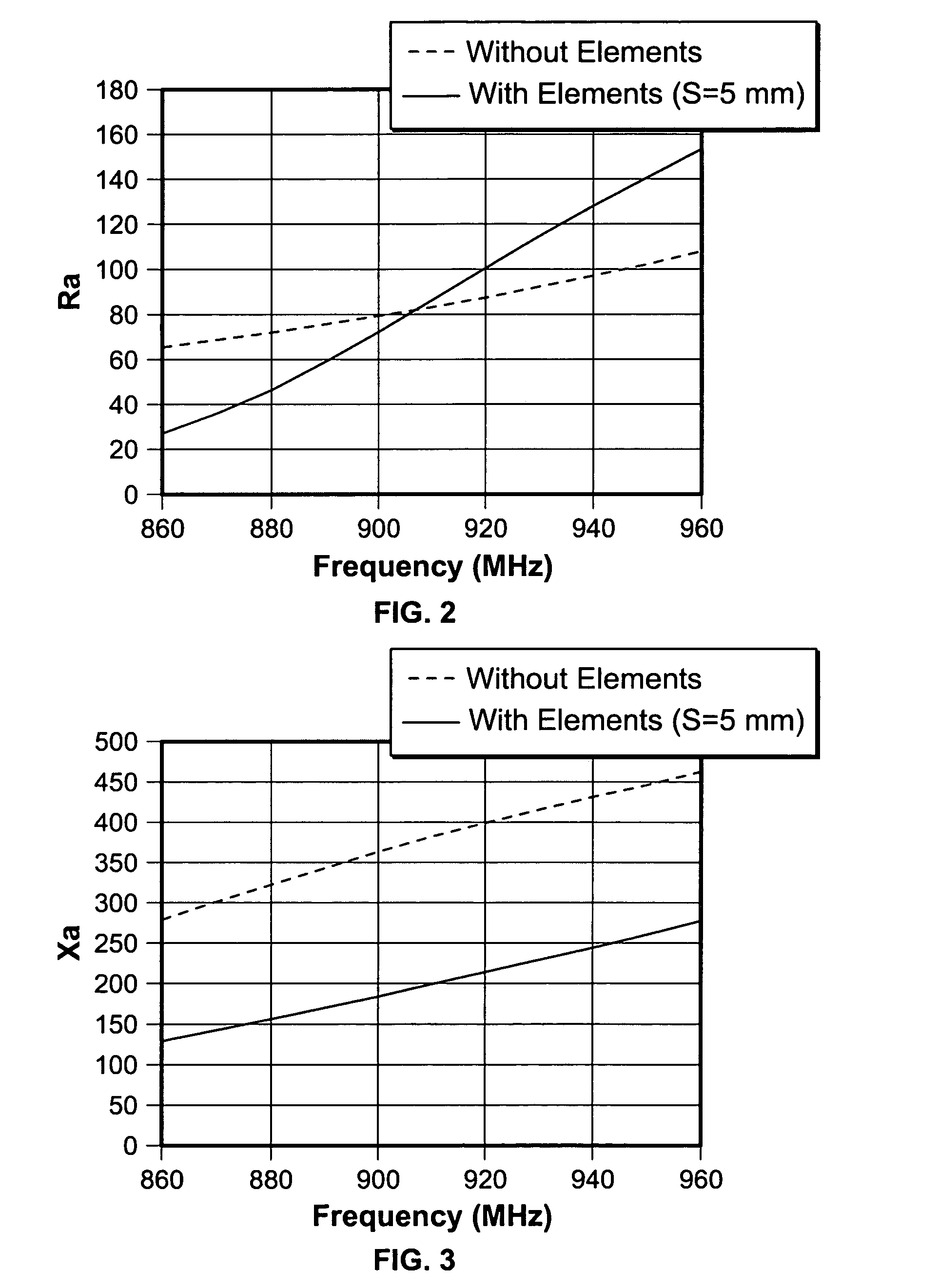
The present invention provides an RF tag that can be customized for use in different geographic regions. This is achieved by tuning the antenna of the RF tag using a parasitic element that interacts with the antenna to affect its impedance. The orientation of the parasitic element is selected to achieve a desired operational frequency band for the RF tag. The RF tag can be affixed to a substrate layer or printed on an insert card and adhesively coupled to the substrate layer. The technical effect of this invention is that it allows for the creation of RF tags that can be tailored for specific regions, making them more efficient and effective in their usage.

Problems solved by technology

Further, the RFID tag memory may be re-written with new or additional data, which would not be possible with a printed bar code symbol.
But, a drawback of using the UHF RFID tags is that there isn't one single global standard for UHF communications.
The North-American UHF standard (908-928 MHz) is not accepted in France as it interferes with its military bandwidths.
Thus, RFID tags communicating in the UHF spectrum must be specifically tuned for each regional / national application, and there is no single UHF RFID tag available for global use.

Method used


Image

  • Tunable RFID tag for global applications
  • Tunable RFID tag for global applications
  • Tunable RFID tag for global applications

Examples


Embodiment Construction

[0022]The present invention satisfies the need for an RF tag that can be tuned for use under any national or regional standards. In the detailed description that follows, like element numerals are used to describe like elements illustrated in one or more of the figures.

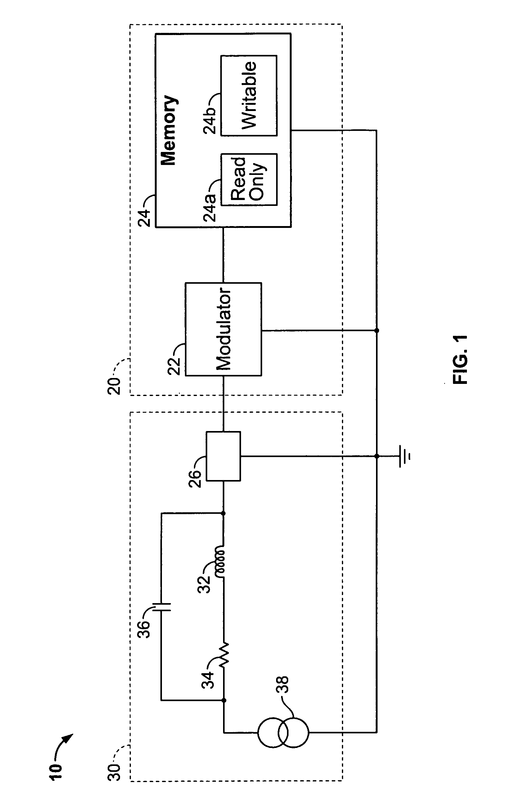
[0023]Referring first to FIG. 1, an exemplary circuit schematic of an RF tag 10 is shown. The RF tag 10 includes a transponder circuit 20 and an antenna 30. The transponder circuit 20 further includes a modulator 22 and a memory 24. The modulator 22 provides the function of communicating data signals to and from the antenna 30, and the memory 24 provides the function of storing data. The memory 24 may further include a read-only portion 24A that includes data that may not be altered, and a writable portion 24B that may be selectively written-to by a remote interrogator. The transponder circuit may further comprise an RFID transponder, such as disclosed by U.S. Pat. No. 4,786,907, issued Nov. 22, 1998, for “Transponder...


PUM


Abstract

An RF transponder comprises a transponder integrated circuit, an antenna connected to the transponder integrated circuit, and at least one parasitic element adapted to interact electrically with the antenna and thereby affect antenna impedance. The orientation of the parasitic element with respect to the antenna is selected to achieve a desired operational frequency band for the RF transponder. Specifically, the spacing between the antenna and the parasitic element is selected to achieve the desired operational frequency band. For example, a first selected spacing may enable an operational frequency band suitable for a first geographic region (e.g., the United States), a second selected spacing may enable an operational frequency band suitable for a second geographic region (e.g., Europe), and a third selected spacing may enable an operational frequency band suitable for a third geographic region (e.g., Japan).

Description

BACKGROUND OF THE INVENTION[0001]1. Field of the Invention[0002]The present invention relates to radio frequency identification (RFID) systems. More particularly, the invention relates to a tag containing an RFID transponder having an antenna that can be easily tuned for use throughout the world in accordance with any national or regional standards.[0003]2. Description of Related Art[0004]Radio frequency transponders are used in many applications. In the automatic data identification industry, the use of RFID transponders (also known as RFID tags) has grown in prominence as a way to obtain data regarding an object onto which an RFID tag is affixed. An RFID tag generally includes a memory in which information may be stored. An interrogator containing a transmitter-receiver unit is used to query an RF tag that may be at a distance from the interrogator and moving relative to the interrogator. The RFID tag detects the interrogating signal and transmits a response signal containing enco...

Claims


Application Information

Patent Timeline
Patent Type & Authority Patents(United States)
IPC IPC(8): G08B26/00G08B13/14H01Q21/12
CPCG06K19/0724G06K19/0726G06K19/07749G06K19/07786
Inventor KODUKULA, VENKATA S.NIKITIN, PAVELLAM, FOR SANDER
Owner INTERMEC IP
Learn More