Quality of service functions implemented in input interface circuit interface devices in computer network hardware

a technology of input interface circuit and computer network hardware, applied in data switching networks, frequency-division multiplexes, instruments, etc., can solve problems such as decision to discard packets, unnecessary waste of bandwidth, and disadvantages of qos installations

Inactive Publication Date: 2005-03-22
IBM CORP
View PDF7 Cites 31 Cited by
  • Summary
  • Abstract
  • Description
  • Claims
  • Application Information

AI Technical Summary

Benefits of technology

A distinguishing characteristic of the present invention is that the transmit / discard decision is made upstream of routine switch functions. Therefore, the present invention prevents or reduces switch congestion by proactively discarding datagrams that would not survive processing through a switch anyway. The present invention thereby releases computing and storage resources for processing the more valuable types of traffic when congestion of finite resources makes processing of all datagrams impossible.
Yet another aspect of the excess bandwidth signal that specifically relates to the present invention is the combination of multiple excess bandwidth indications, each relating to different output ports, into a single physical signal, possibly a Time Division Multiplex (TDM) signal, enabling flow control actions to be focused on those output ports experiencing congestion.

Problems solved by technology

Such intuitive methods require tuning of the thresholds as offered loads change, a major disadvantage to their use in Quality of Service (QoS) installations.
Another drawback with the prior art techniques is that the decision to discard a packet is made in the switch and / or after some type of processing is already performed on the packet.
Partially processing a packet and then discarding it results in unnecessary waste of bandwidth.

Method used


Image

  • Quality of service functions implemented in input interface circuit interface devices in computer network hardware
  • Quality of service functions implemented in input interface circuit interface devices in computer network hardware
  • Quality of service functions implemented in input interface circuit interface devices in computer network hardware

Examples


Embodiment Construction

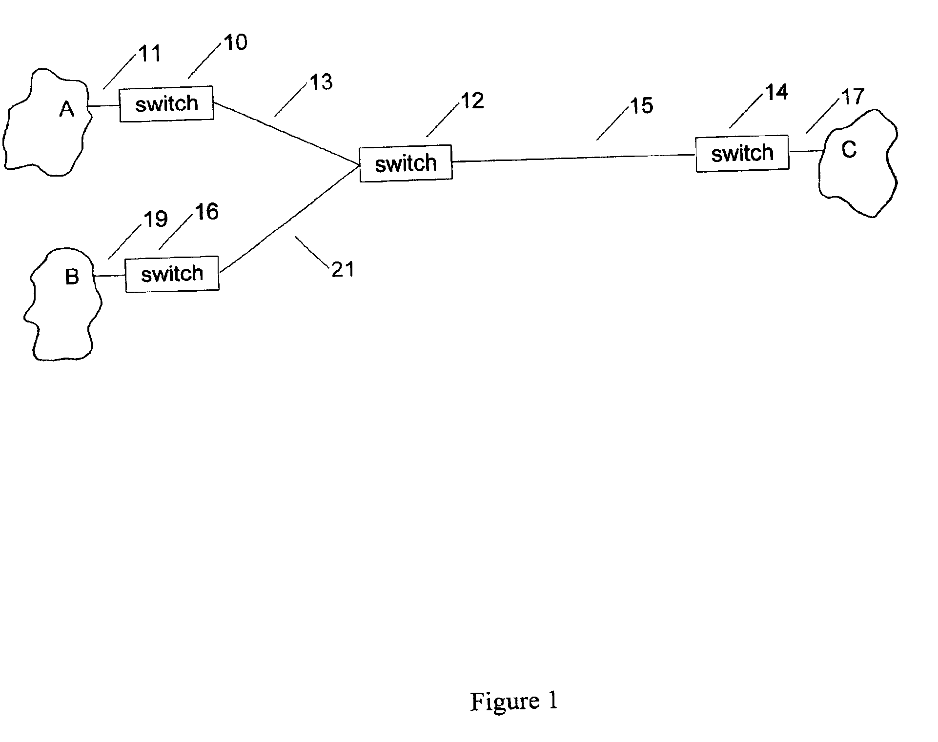
FIG. 1 shows an abstraction of a computer network including Local Area Networks (LANs) A, B, C. These LANs may include workstations, servers, storage devices, or other computers that exchange information in a network. The network may also include an infrastructure of switches 10, 12, 14, 16, as well as communications links 11, 13, 15, 17, 19, 21 between pairs of switches or between LANs and switches. Thus a computer network is organized as a graph with vertices (computers and switches) and edges (communications links). In general terms, the purpose of the invention described herein is to promote movement of data within the computer network efficiently and fairly, taking into account certain contracts pertaining to the availability and quality of service, the contracts being held by consumers of computer network services.

a) Quality of Service

The overall goal, according to the present invention, of moving flow control upstream of the switch is to more closely approximate a kind of ide...


PUM


Abstract

The decision to discard or forward a packet is made by a flow control mechanism, upstream from the forwarding engine in the node of a communication network. The forwarding engine includes a switch with mechanism to detect congestion in the switch and return a binary signal B indicating congestion or no congestion. The flow control mechanism uses B and other network related information to generate a probability transmission table against which received packets are tested to determine proactively whether a packet is to be discarded or forwarded.

Description

BACKGROUND OF THE INVENTION1. Technical FieldThe present invention relates to congestion management in computer networks in general and, in particular, to flow control by network hardware.2. Prior ArtA switch is a network node that directs datagrams on the basis of Medium Access Control (MAC) addresses, that is, Layer 2 in the OSI model well known to those skilled in the art [see “The Basics Book of OSI and Network Management” by Motorola Codex from Addison-Wesley Publishing Company, Inc., 1993]. A switch can also be thought of as a multiport bridge, a bridge being a device that connects two LAN segments together and forwards packets on the basis of Layer 2 data. A router is a network node that directs datagrams on the basis of finding the longest prefix in a routing table of prefixes that matches the Internet Protocol (IP) destination addresses of a datagram, all within Layer 3 in the OSI model. The present invention considers a network node to be a switch, a router, or, more gener...

Claims


Application Information

Patent Timeline
Patent Type & Authority Patents(United States)
IPC IPC(8): H04L12/56
CPCH04L47/10H04L47/32H04L47/12H04L47/129H04L12/00
Inventor BARKER, KENNETH JAMESDAVIS, GORDON TAYLORJEFFRIES, CLARK DEBSRINALDI, MARK ANTHONYSUDEEP, KARTIK
Owner IBM CORP
Why Eureka
Try Eureka