Camshaft adjuster for internal combustion engines of motor vehicles

a technology for internal combustion engines and camshafts, which is applied in the direction of valve details, couplings, mechanical equipment, etc., can solve the problems of difficult mounting of valves in internal combustion engines of motor vehicles

Inactive Publication Date: 2005-03-29
HYDRAULIK RING
View PDF8 Cites 22 Cited by
  • Summary
  • Abstract
  • Description
  • Claims
  • Application Information

AI Technical Summary

Benefits of technology

According to another embodiment, the valve is arranged at least partially within the camshaft adjuster. In this way, no additional mounting space for the valve in the internal combustion engine is required.

Problems solved by technology

Often it is difficult to mount the valve in the internal combustion engine of the motor vehicle because there is not enough space.

Method used


Image

  • Camshaft adjuster for internal combustion engines of motor vehicles
  • Camshaft adjuster for internal combustion engines of motor vehicles
  • Camshaft adjuster for internal combustion engines of motor vehicles

Examples


Embodiment Construction

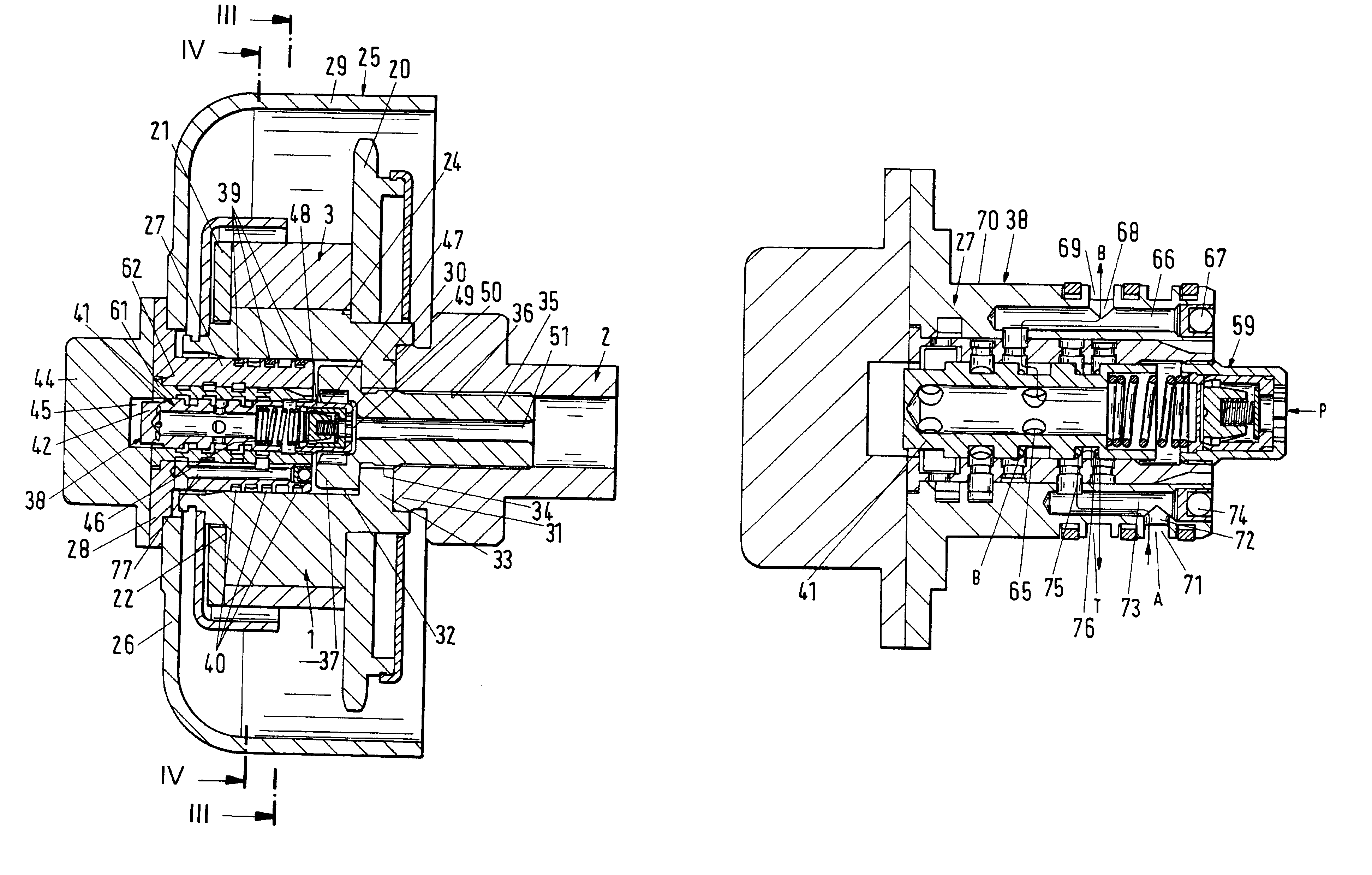
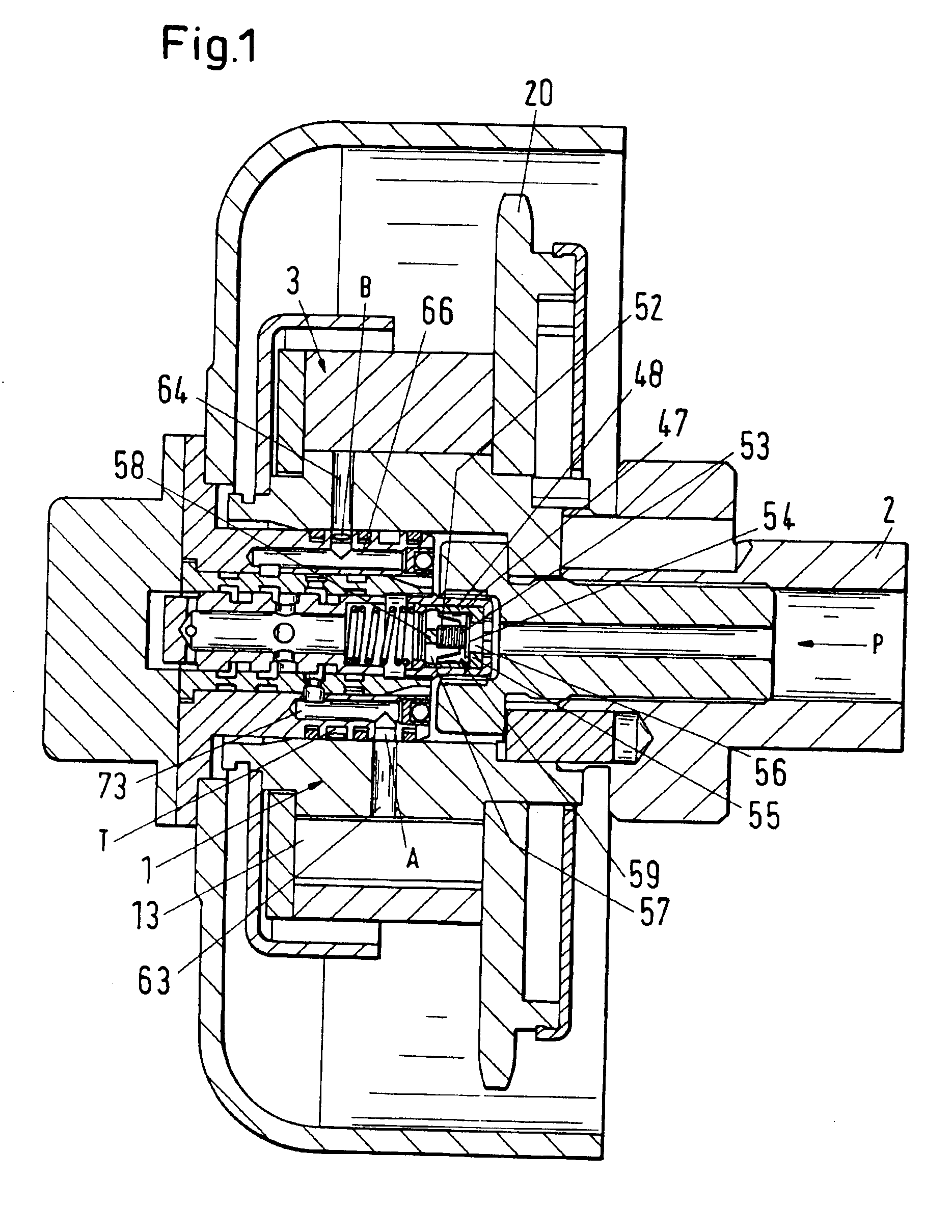
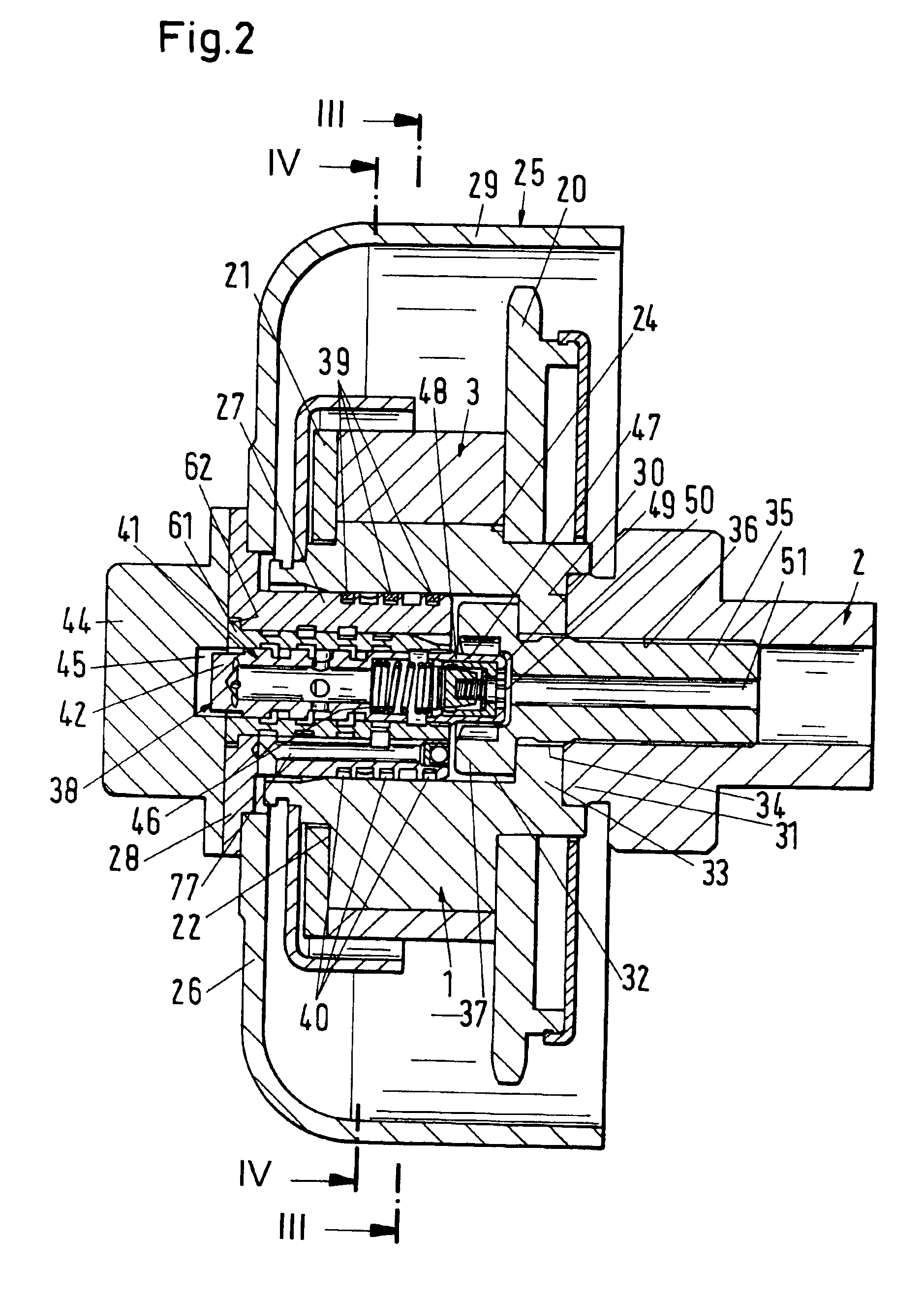
The camshaft adjuster according to FIGS. 1 through 4 serves for adjusting the timing of opening of the intake and exhaust valves of an internal combustion engine of a motor vehicle in accordance with the output requirement of the engine. Such camshaft adjusters are known and will therefore be explained only briefly.

The camshaft adjuster has a rotor 1 which is connected fixedly to the camshaft 2. The rotor 1 is surrounded by a stator 3. It has a cylindrical jacket 4 provided on its inner wall with radially inwardly projecting stays 5 that are uniformly spaced from one another. They are identical and rest with their end faces 6 areally against an outer cylindrical peripheral surface 7 of a base member 8 of the rotor 1. Radially outwardly projecting stays 9 that are uniformly spaced project from the rotor and rest with their end faces areally and sealingly against an inner cylindrical peripheral surface 11 of the jacket 4 of the stator 3. The stays 5, 9 of the stator 3 and of the rotor...


PUM


Abstract

A camshaft adjuster for motor vehicles has a stator and a rotor rotatable relative thereto between which pressure chambers are provided. Pressure medium is supplied in a controlled way via a valve to the pressure chambers in order to rotate the rotor relative to the stator. Mounting of the valve in the internal combustion engine of the motor vehicle is often difficult when mounting conditions are tight, sometimes even impossible. In order for the camshaft adjuster to be usable even in tight spatial conditions, the valve is arranged on the side facing away from the camshaft connection. The valve can therefore be arranged stationarily axially outside of the engine of the motor vehicle. The camshaft adjuster requires thus only little mounting space.

Description

BACKGROUND OF THE INVENTIONThe invention relates to a camshaft adjuster for internal combustion engines of motor vehicles comprising a stator and a rotor rotatable relative to the stator, between which pressure chambers are provided that are connected by lines with at least one valve via which pressure medium is supplied to the pressure chambers, respectively.By means of camshaft adjusters, the timing of opening of intake and exhaust valves of internal combustion engines is controlled as a function of the output required at the moment. Often it is difficult to mount the valve in the internal combustion engine of the motor vehicle because there is not enough space.SUMMARY OF THE INVENTIONIt is an object of the invention to configure the camshaft adjuster of the aforementioned kind such that it can be used even in tight space conditions in the motor vehicle.This object is solved according to the invention for the camshaft adjuster of the aforementioned kind in that the valve is arrang...

Claims


Application Information

Patent Timeline
Patent Type & Authority Patents(United States)
IPC IPC(8): F01L1/344
CPCF01L1/022F01L1/3442F01L1/024F01L2001/34483F01L2001/34433F01L2001/34436F01L2001/3444F01L2001/34426F01L2250/02F01L2250/04F01L2250/06
Inventor PALESCH, EDWINKNECHT, ANDREASSLUKA, GEROLD
Owner HYDRAULIK RING
Why Eureka
Try Eureka