Multi-flow pour spout and adapter

a multi-flow, pouring technology, applied in the direction of liquid transfer devices, liquid handling, packaging goods types, etc., can solve the problems of potential spills, health and safety risks of spilled fuel, and spills in general, so as to achieve the effect of avoiding potential spills and avoiding the possibility of spills

Inactive Publication Date: 2005-03-29
MIDWEST CAN
View PDF40 Cites 20 Cited by
  • Summary
  • Abstract
  • Description
  • Claims
  • Application Information

AI Technical Summary

Benefits of technology

In a first embodiment, a pour spout for transferring fluid from a container to a vessel is provided. The pour spout comprises a base having an inner sleeve extending outwardly therefrom, a conduit member located in the inner sleeve, and an outer sleeve slidingly engaging the inner sleeve. The conduit member has a fluid tube, an air tube and an end cap. The outer sleeve is in a first closed position wherein the outer sleeve contacts the end cap preventing fluid flow from the pour spout. The pour spout can only be opened by rotating the outer sleeve to a first or second indexed position. By rotating the outer sleeve relative to the inner sleeve, the outer sleeve is adapted to be slid to a first open position permitting fluid to flow at a first flow rate through the fluid tube and out of the pour spout. By further rotating the outer sleeve, the outer sleeve is adapted to be slid to a second open position permitting fluid to flow at a second flow rate through the fluid tube at a second flow rate and out of the pour spout.

Problems solved by technology

Spilled fuel presents health and safety risks to people and the environment in general.
The opportunity for spills have various causes.
First, often times the gas tanks in the aforementioned internal combustion engines have very narrow openings which requires precise pouring and / or a facilitating pour spout or funnel to prevent spills.
Many times spills occur because the operator of the pour spout does not know when the receiving vessel is full.
Yet another cause of spills is the ineffective venting of the container from which the fluid is being transferred.
The result of ineffective venting is an uneven fluid flow, and even in some cases surging of the fluid.
Surges can cause splashing and an uneven flow makes it extremely difficult to predict fluid levels in the receiving vessel.
Another problem encountered by gravity influenced pour spouts is airlock caused by improper venting.
Airlock occurs as a result of improper venting in combination with specific volume and viscosity parameters of the fluid being transferred.
Such a condition can result in fluid which will not pour even when the container is inverted.
However, this only increases the opportunity for spills.
These pour spouts all have at least the following drawbacks: they do not provide multiple flow rate options and they do not provide childproof locks.
Additionally, known pour spouts are limited in their compatibility with multiple vessel types, especially in light of certain state regulations requiring specific spout diameters for certain applications.
This poses a problem if one desires to use the same spout for filling a fuel tank of an automobile, the fuel tank receptacle of which has a standard size opening of ¾ inch.

Method used


Image

  • Multi-flow pour spout and adapter
  • Multi-flow pour spout and adapter
  • Multi-flow pour spout and adapter

Examples


Embodiment Construction

While this invention is susceptible of embodiment in many different forms, there is shown in the drawings, and will be described herein in detail, specific embodiments thereof with the understanding that the present disclosure is to be considered as an exemplification of the principles of the invention and is not intended to limit the invention to the specific embodiments illustrated.

Pour Spout

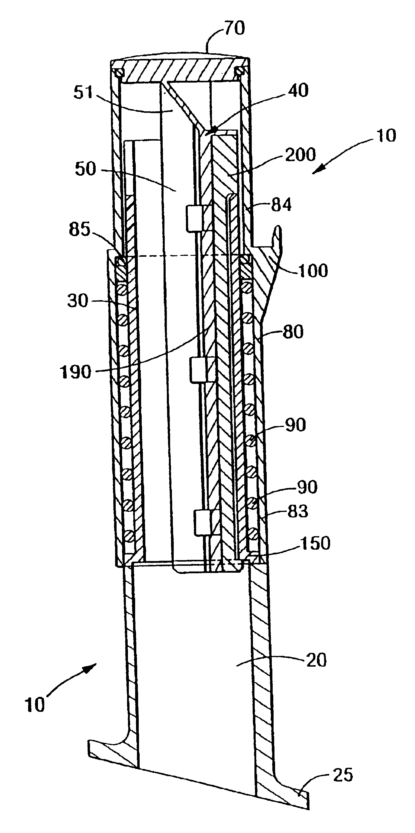
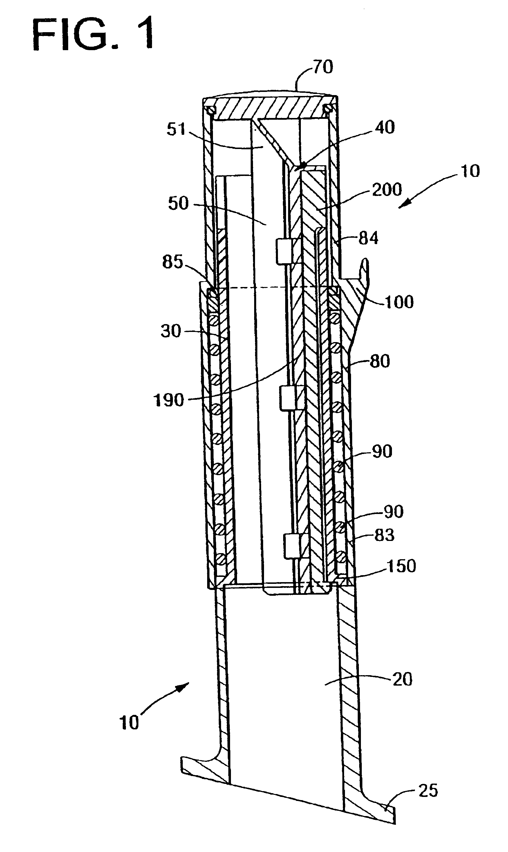
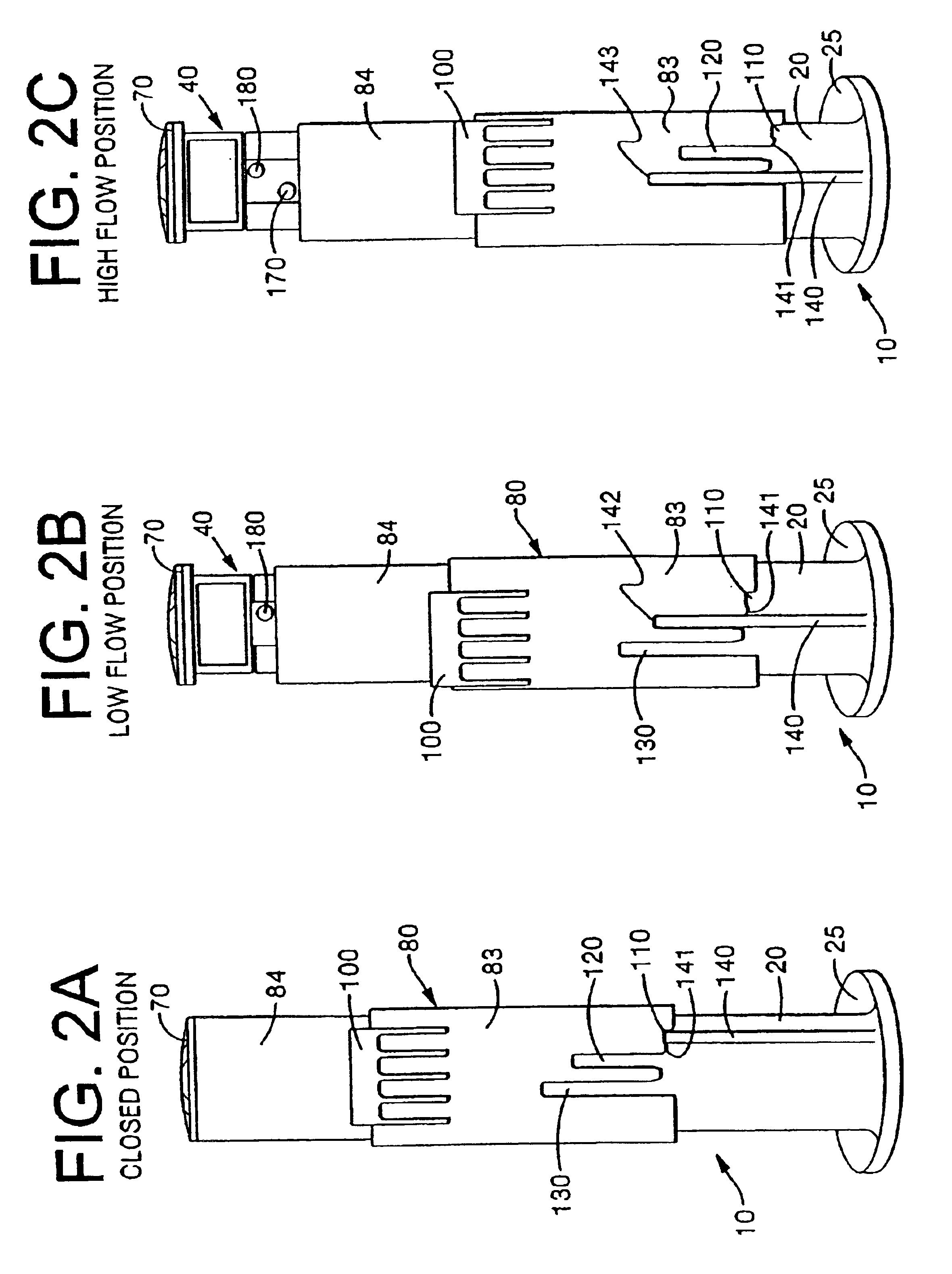
Referring to FIGS. 1-13 there is shown a spill-proof pour spout 10 according to a preferred embodiment of the present invention. As shown in FIG. 1, the spill-proof pour spout 10 includes a base 20 having an inner sleeve 30 extending outwardly therefrom. A conduit member 40 is located in the inner sleeve 30 and includes a fluid tube 50, a first and a second air tube 60, 61 (see FIG. 9) and an end cap 70. An outer sleeve 80 engages the inner sleeve 30 and is held in a normally closed position by a biasing member 90, such as a spring or elastomeric member. In the normally closed position, the ou...


PUM

PropertyMeasurementUnit
diameteraaaaaaaaaa
flow rateaaaaaaaaaa
air flow rateaaaaaaaaaa

Abstract

A spill-proof pour spout for transferring fluid from a container to a vessel comprising a base having an inner sleeve extending outwardly therefrom, a conduit member located in the inner sleeve, and an outer sleeve slidingly engaging the inner sleeve. The conduit member has a fluid tube, and air tube and an end cap. The outer sleeve is in a first closed position wherein the outer sleeve contacts the end cap preventing fluid flow from the pour spout. The pour spout can only be opened by rotating the outer sleeve to a first or second indexing position. By rotating the outer sleeve either clockwise or counterclockwise relative to the inner sleeve, the outer sleeve is adapted to be slid to a first open position permitting fluid to flow at a first flow rate through the fluid tube and out of the pour spout. By further rotating the outer sleeve either clockwise or counterclockwise, the outer sleeve is adapted to be slid to a second open position permitting fluid to flow at a second flow rate through the fluid tube at a second flow rate and out of the pour spout.

Description

BACKGROUND OF THE INVENTIONThis invention relates to pour spouts for containers of fluid, and more particularly to pour spouts which permit transfers of fluid (liquid) based on the influence of gravity at multiple flow rates, and without the risk of spills or overflow, and also to adapters that can be affixed to pour spouts for desirous results.It is desirable to avoid overfilling of fuel to internal combustion engines in lawnmowers, tractors, personal water craft, chain saws and power tools, outboard motors, ATV recreational vehicles and even automobiles. Spilled fuel presents health and safety risks to people and the environment in general. As a result, many states have now passed environmental legislation which regulates pour spouts which can be used in conjunction with volatile fuels and other liquids.The opportunity for spills have various causes. First, often times the gas tanks in the aforementioned internal combustion engines have very narrow openings which requires precise ...

Claims


Application Information

Patent Timeline
Patent Type & Authority Patents(United States)
IPC IPC(8): B67D5/01B67D7/00
CPCB67D7/005
Inventor TRIPPI, JR., JOHN
Owner MIDWEST CAN
Why Eureka
Try Eureka