Waterproof connector with waterproof rib for sealed engagement with a rubber plug

a technology of waterproof connectors and rubber plugs, applied in the direction of coupling bases/cases, coupling device connections, securing/insulating coupling contact members, etc., can solve problems such as inability to achieve waterproofness, and achieve the effect of improving waterproofness of waterproof connectors

Inactive Publication Date: 2005-03-29
SUMITOMO WIRING SYST LTD
View PDF8 Cites 34 Cited by
  • Summary
  • Abstract
  • Description
  • Claims
  • Application Information

AI Technical Summary

Benefits of technology

Since waterproof seal can be accomplished on the side or peripheral surface of the rubber plug, the waterproofness of the waterproof connector can be improved to a higher extent.

Problems solved by technology

As a result, there is a possibility that waterproofness is not obtained at the gap between the rubber plug 5 and the sealing surface 8.

Method used


Image

  • Waterproof connector with waterproof rib for sealed engagement with a rubber plug
  • Waterproof connector with waterproof rib for sealed engagement with a rubber plug
  • Waterproof connector with waterproof rib for sealed engagement with a rubber plug

Examples


first embodiment

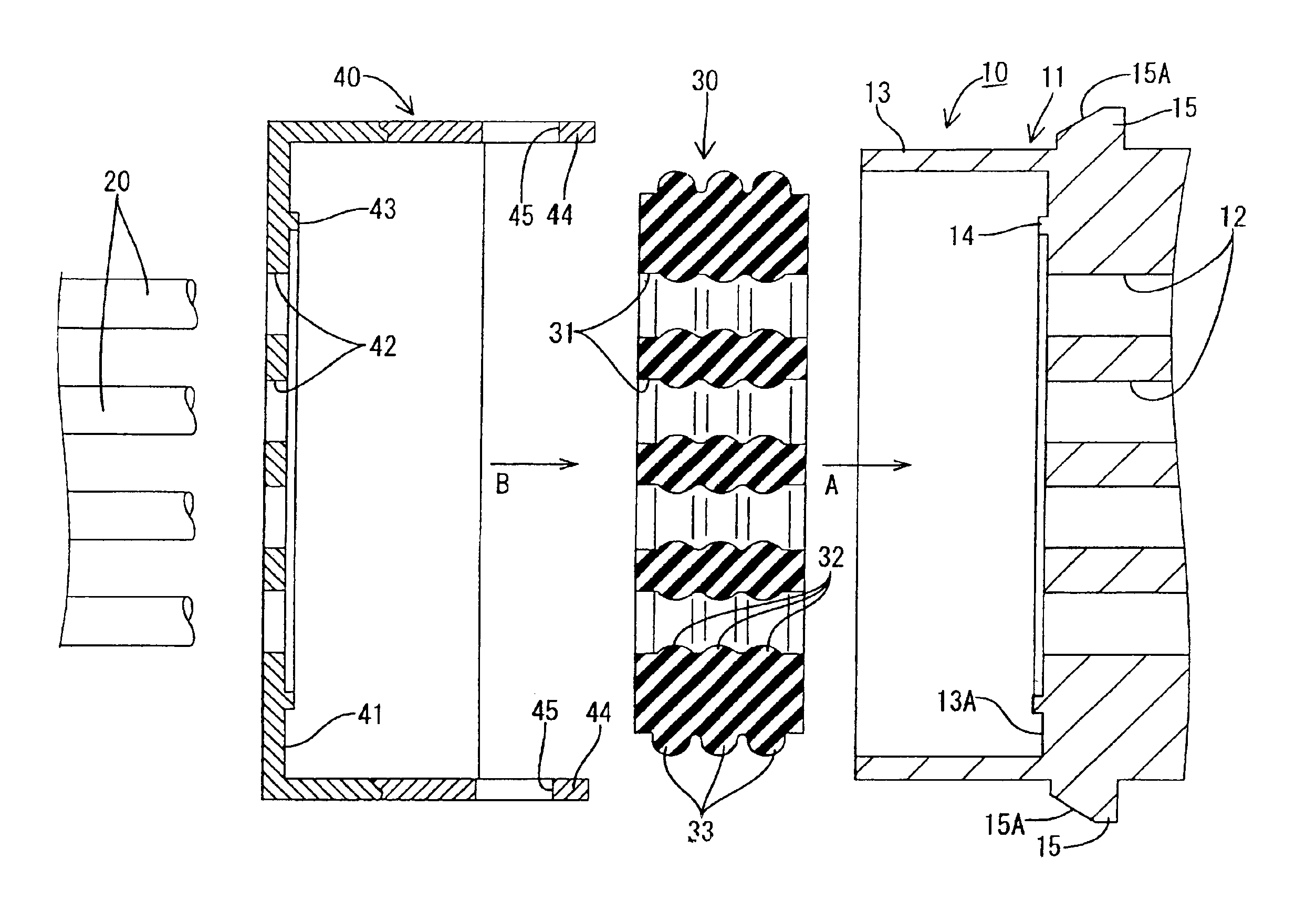
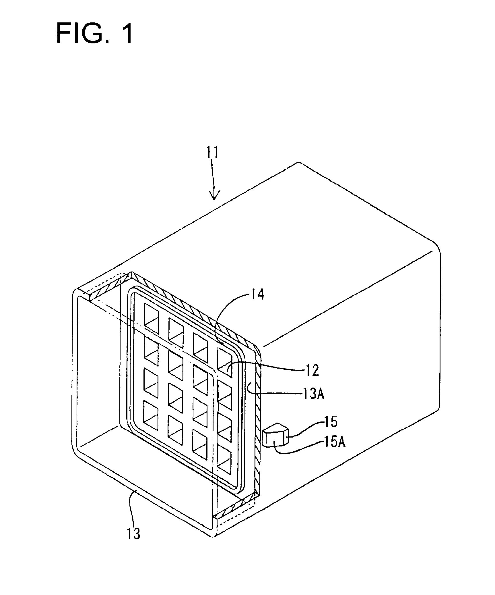
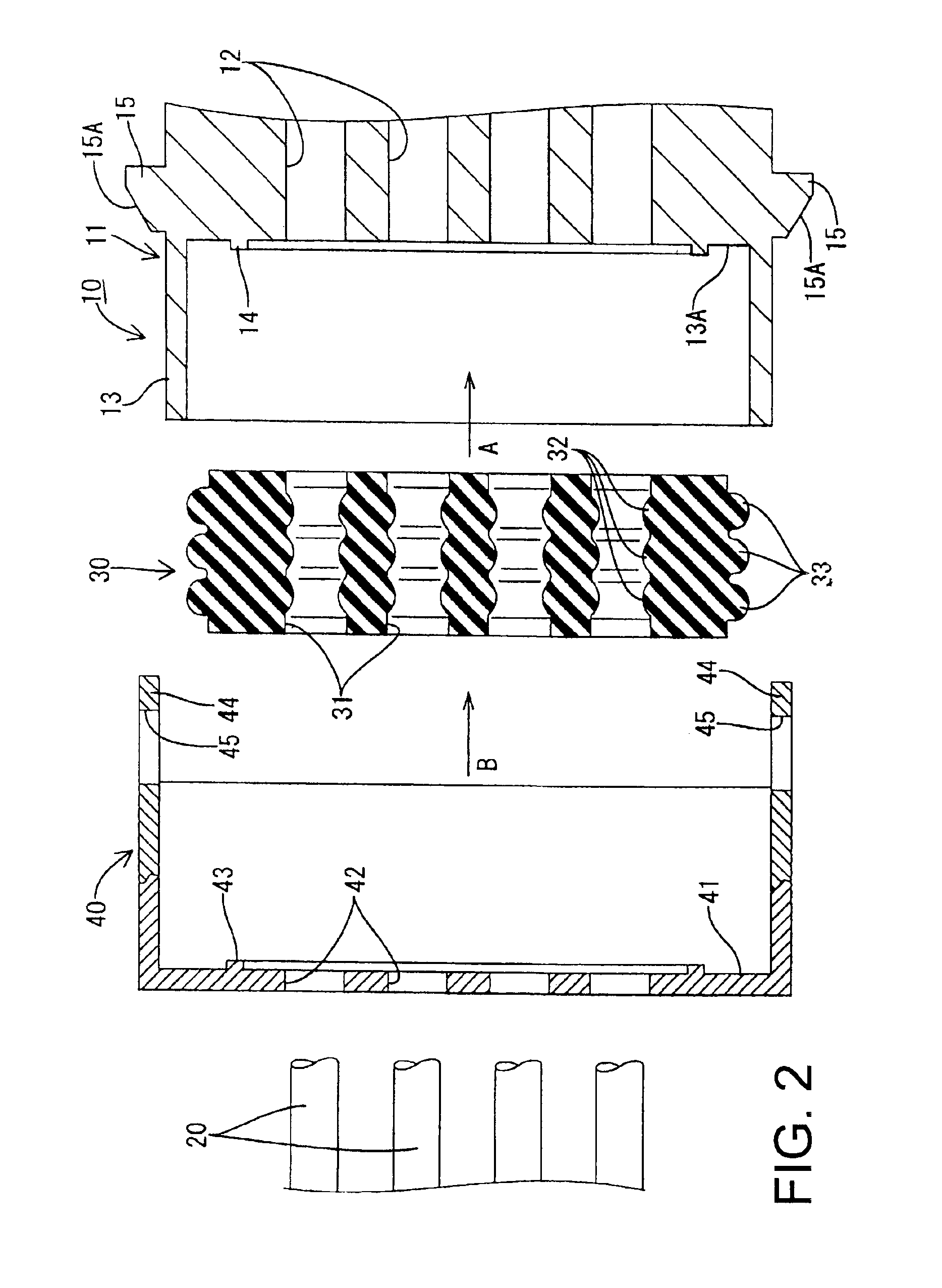
A waterproof connector according to the present invention is identified by the numeral 10 in FIGS. 1 through 4. The waterproof connector 10 includes a connector housing 11 capable of fitting on an unshown mating connector. In the description made hereinafter, the front side means the right inward side in FIG. 1.

The waterproof connector 10 shown in FIGS. 2 and 4 is box-shaped and has the connector housing 11 made of a synthetic resin. As shown in FIG. 1, cavities 12 are arranged in four steps and four rows inside the waterproof connector 11. The cavities 12 penetrate through the connector housing 11 in a front-to-back direction. Unshown terminal fittings to which electric wires 20 have been crimped respectively are inserted into the cavities 12 in a direction from the rear thereof and are accommodated in the cavities 12. When the waterproof connector 10 fits on the mating connector, the terminal fittings can be connected electrically to terminal fittings of the mating connector. A re...

second embodiment

A connector according to the present invention is identified by the numeral 10A in FIGS. 5 through 8.

In the second embodiment, the contact surface 13A of the rubber plug accommodation part 13 has an inner-side waterproof rib 14A formed for the rear open end of each cavity 12. Additionally, the hold-down surface 41 of the rubber plug hold-down member 40 has an outer-side waterproof rib 43A formed for each insertion opening 42 corresponding to the rear open end of the cavity 12.

Other constructions of the connector 10A of the second embodiment are similar to that of the connector 10 of the first embodiment. Parts of the second embodiment having the same function as those of the first embodiment are denoted by the same reference numerals as those of the first embodiment and description thereof is omitted herein.

In the second embodiment, the second and third water penetration paths accomplish waterproofing at the rear open end of each cavity 12 or at each insertion opening 42. That is, t...


PUM


Abstract

A rear open end of each cavity (12) is formed on a contact surface (13A) of a rubber plug accommodation part (13) disposed rearward from the connector housing (11). Inner-side waterproof ribs (14) project rearward from the periphery of the contact surface (13A) to surround the rear open ends. A rubber plug (30) is held inside the rubber plug accommodation part (13) by a rubber plug hold-down member (40) mounted on the waterproof connector (11) rearward of the rubber plug (30). Thus, the rubber plug hold-down member (40) presses the rubber plug (30) forward against the contact surface (13A). The inner-side waterproof rib (14) prevents water from penetrating into the cavity (12) from the gap between the contact surface (13A) and a front surface of the rubber plug (30) through a peripheral surface of the rubber plug (30).

Description

BACKGROUND OF THE INVENTION1. Field of the InventionThe present invention relates to a waterproof connector.2. Description of the Related ArtU.S. Pat. No. 5,871,373 and FIG. 9 herein disclose a multi-polar plug hold-down member. With reference to FIG. 9, a waterproof connector 1 has a housing 2, and terminal fittings 3 are accommodated respectively in cavities 4 arranged inside the housing 2. A rubber plug 5 is fit in a rubber plug accommodation hole 6 on the rear surface of the housing 2 to prevent water from penetrating into the cavities 4. A rubber plug hold-down member 7 is disposed in the rear of the rubber plug 5 and holds the rubber plug 5. A waterproof seal is provided in the waterproof connector 1 by bringing the rubber plug 5 into close contact with a sealing surface 8, which is the inner peripheral surface of the rubber plug accommodation hole 6.The housing 2 may have to be large to multi-polarize the waterproof connector 1. In this situation, the width of the rubber plug...

Claims


Application Information

Patent Timeline
Patent Type & Authority Patents(United States)
IPC IPC(8): H01R13/52
CPCH01R13/5208
Inventor OKA, HIROYUKI
Owner SUMITOMO WIRING SYST LTD
Why Eureka
Try Eureka