Rendering deformable 3D models recovered from videos

a 3d model and video technology, applied in the field of computer vision, can solve the problems of not addressing the case of both unconstrained motion and no prior understanding of shape and motion

Inactive Publication Date: 2005-03-29
MITSUBISHI ELECTRIC RES LAB INC
View PDF3 Cites 39 Cited by
  • Summary
  • Abstract
  • Description
  • Claims
  • Application Information

AI Technical Summary

Benefits of technology

The invention provides a “parsimony” constraint, and uses the constraint to correct any undesirable properties of the SVDs. In addition, the invention provides improved and generalized methods for factorizatio...

Problems solved by technology

However, they do not address the case of both unconstrained motion an...

Method used


Image

  • Rendering deformable 3D models recovered from videos
  • Rendering deformable 3D models recovered from videos
  • Rendering deformable 3D models recovered from videos

Examples


Embodiment Construction

Method Overview

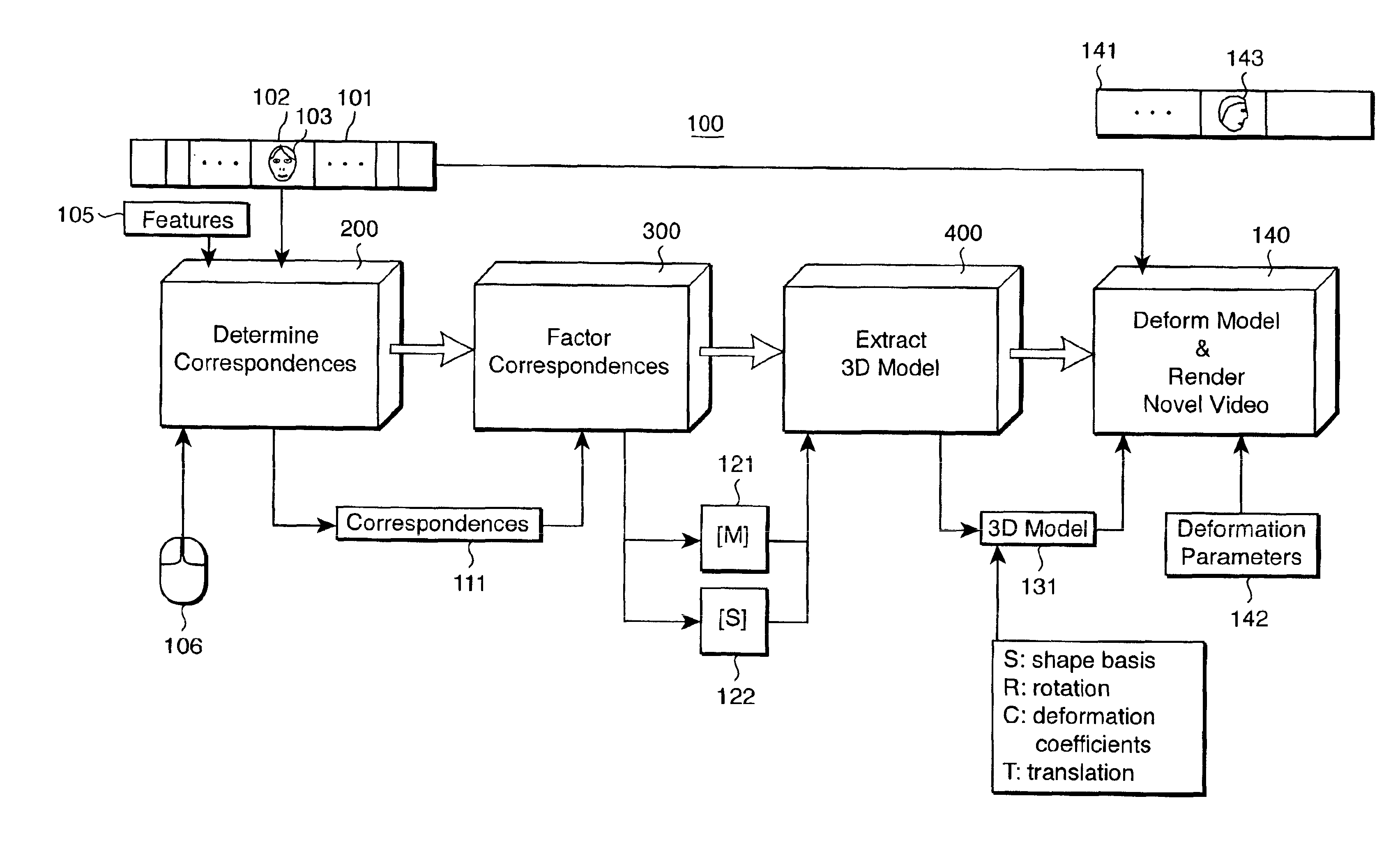
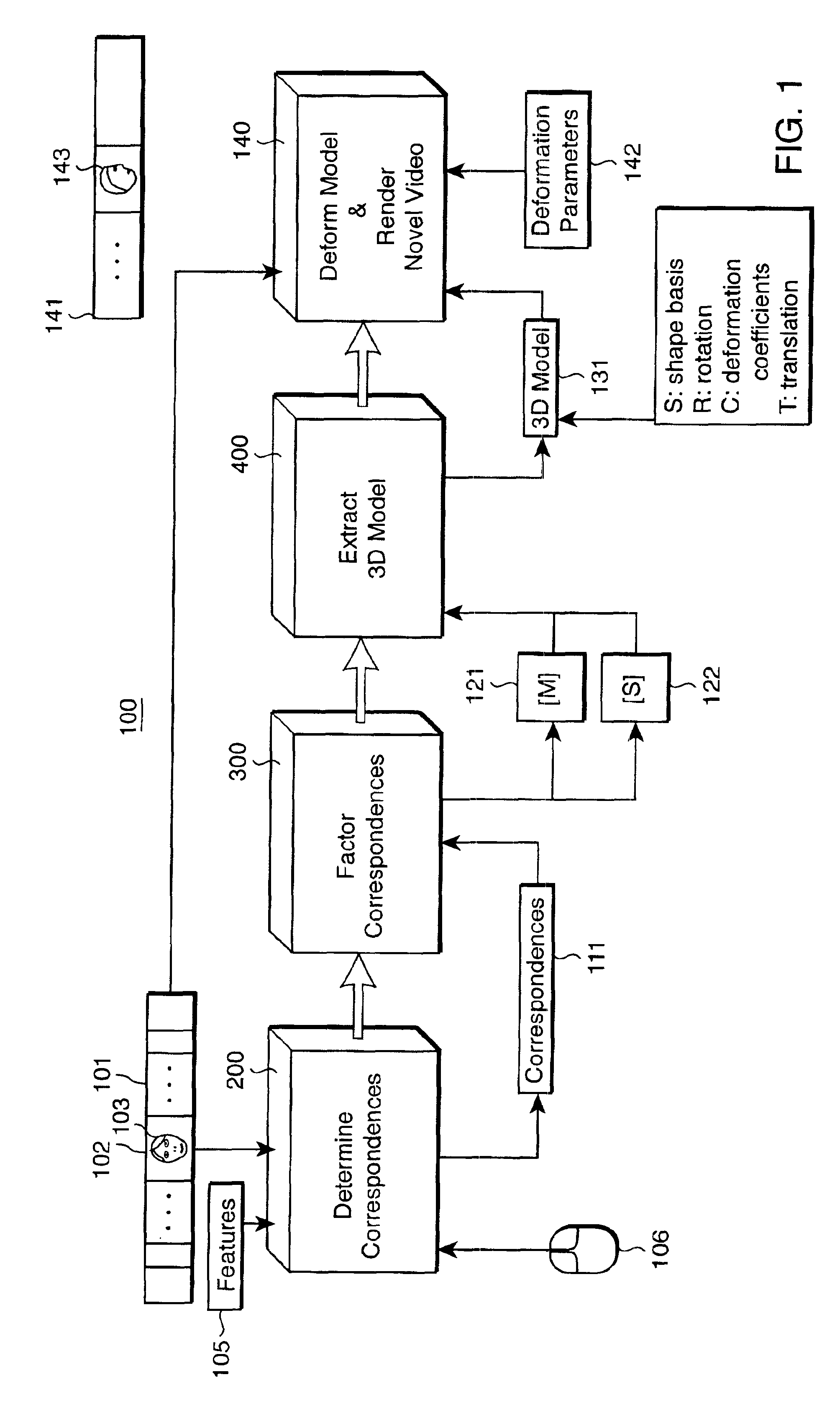
FIG. 1 shows a method 100 according to my invention. The method 100 recovers a non-rigid 3D shape and motion model 131 of an object or a scene directly from an input video 101 obtained by a camera. For example, the video is of a “talking head”103 seen face on. Techniques and machinery for acquiring images by video or movie cameras are well known.

First, a reference image 102 is selected. The reference image 102 can be any image in the video that is consistent with the general shape and appearance of the object of interest throughout the video, for example, the middle image. Correspondences 111 are then determined 200 for a set of features 105 of the object in each image of the video.

The features 105 can be selected manually or automatically. For example, a pointing device 106 can be used to “click” on a relatively small number of features in the reference image 102. The number of features depends on the desired amount of detail in the final 3D model. For faces, 80-100 ...


PUM


Abstract

A method recovers a 3D model of non-rigid 3D shape and motion of an object directly from an input video of the object by first identifying a set of features on the object in a reference image of the input video. Correspondences are then determined between the set of features in the reference image and corresponding features in each other image of the input video, These correspondences are factored by cascaded singular value decompositions into a motion matrix and a shape matrix. The 3D model can then be extracted from the factored motion matrix and shape matrix. The 3D model includes a linear basis for deformable shape of the object in the input video, and for each image a 3D rotations matrix, deformation coefficients, and translation vectors. A novel video can now be generated from the input video by manipulating the 3D model.

Description

FIELD OF THE INVENTIONThe present invention relates generally to the field of computer vision, and particularly to recovering 3D models including shape, motion, and deformation of non-rigid objects from videos so that videos can be rendered in a novel manner.BACKGROUND OF THE INVENTIONThe problem of recovering 3D deformable models of non-rigid objects from a video is of intense interest in the field of computer vision. Linear models of variability are particularly desirable. For example, eigenface models have been widely used to model 2D image variability since the 1980's. Eigenface models use a variance-reducing dimensionality-reduction for coding and decoding face images, see U.S. Pat. No. 5,164,992 “Face recognition system” issued to Turk, et al. on Nov. 17, 1992. Eigenface methods describe variation between images but do not shed any light on the 3D structure of scenes and objects from which the images were generated.A first class of methods addresses special cases of the recove...

Claims


Application Information

Patent Timeline
IPC IPC(8): G06T7/00G06T7/20G06T17/10G06T1/00G06T19/00
CPCG06T7/0071G06T7/2046G06T17/10G06T2207/30201G06T2207/10016G06T7/579G06T7/251
Inventor BRAND, MATTHEW
Owner MITSUBISHI ELECTRIC RES LAB INC
Why Eureka
Try Eureka