Uniformity compensation in halftoned images

a technology of uniformity compensation and halftones, applied in the field of uniformity compensation of halftones, can solve the problems of image non-uniformities, imaging artifacts in rendered output images, and system components manufactured to higher or more stringent tolerances can be expensive to design and produ

Active Publication Date: 2006-04-13
XEROX CORP
View PDF43 Cites 66 Cited by
  • Summary
  • Abstract
  • Description
  • Claims
  • Application Information

AI Technical Summary

Problems solved by technology

However, imperfections in image rendering systems or processes can lead to image non-uniformities.
For example, in some electrophotographic rendering devices, variation in spot size, as a laser beam, of a raster output scanner, is directed across an imaging surface, such as a photoreceptor or photoconductive substrate, can lead to imaging artifacts in a rendered output image.
Where raster output scanners are based on light emitting diodes, variations in LED efficiency and / or focus can also lead to non-uniformities.
However, system components manufactured to higher or more stringent tolerances can be expensive to design and produce.
However, image descriptions are not always available in terms of contone values.
The limited resolution with which pixels in a halftoned image describe desired lightness levels or shades of gray limits the usefulness of compensating tone reproduction curves for generating compensated values.
Therefore, it has not been possible or practical to use compensating Tone Reproduction Curves to compensate halftoned images for image non-uniformities such as streaks, banding and mottling.

Method used


Image

  • Uniformity compensation in halftoned images
  • Uniformity compensation in halftoned images
  • Uniformity compensation in halftoned images

Examples


first embodiment

[0064] In a first embodiment, if the error is positive, then the error is transferred to the highest valued neighboring pixel that has not yet received an error distribution. The error is transferred up to a maximum value. For example, in a system where an 8-bit value is used to represent gray levels ranging from 0 to 255, 255 may be a maximum value allowed for a pixel. In such a system, where a calculated error is, for example, 100 and the first ranked pixel, or pixel with the highest value, has a pixel value of 220, 35 counts of the calculated error value are transferred to the first ranked pixel. At the end of the operation, the calculated error value is lowered to 65 and the pixel value of the first ranked pixel is raised to the maximum of 255. If, as in the example above, error remains to be diffused or distributed, processing proceeds to an eligible pixel check. In the eligible pixel check, a determination is made as to whether there are additional neighboring pixels available...

fifth embodiment

[0072] Clearly, aspects of these various versions of Rank Ordered Error Diffusion can be combined to create additional versions. For example, the spatial weighting of the fifth embodiment may be combined with the discarding of excess error of the fourth version to create yet another version.

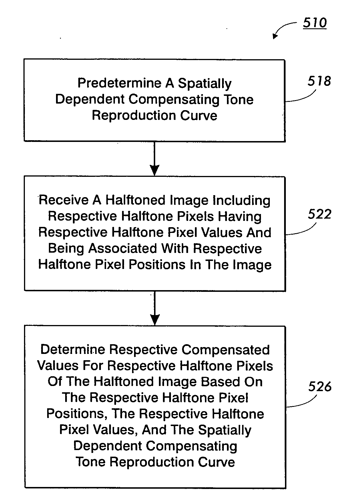
[0073] The method 510 for compensating for a spatial non-uniformity in an image rendering device is applicable where it is appropriate to provide compensation based solely on pixel position. For example, the method 510 is appropriately applied where spatial non-uniformity is not a strong function of pixel value. Additionally, the method 510 is appropriately applied where some compensation is desired, but where the expense of more complete compensation is not warranted. However, some applications may call for additional compensation accuracy.

[0074] Referring to FIG. 6, a second method 610 for compensating for a spatial non-uniformity in an image rendering device includes predetermining 612 a spat...


PUM


Abstract

Compensation for rendering device non-uniformities is provided for halftoned images. A spatially dependent tone reproduction curve (TRC) provides compensation values. Pixel location information is used to access TRC values. For example, the values are modification values. The modification values are added to the pixel values to generate combined values. Quantization is applied to the combined values to prepare compensated image data for rendering. For example, Rank Ordered Error Diffusion is applied to the combined values. The combined values may include diffused error from previously processed pixels. Gray values may be estimated for the respective pixels. The estimated gray values may be used to access compensation information from a TRC that is both spatially and gray value dependent. Mathematical basis decomposition is used to reduce TRC memory requirements. For example, Discrete Cosine Transformation, Singular Value Decomposition or Principal Component Analysis is used to determine a compact form for the TRC.

Description

BACKGROUND [0001] The present exemplary embodiment relates to methods and systems for improving image uniformity in image rendering systems. It finds particular application in conjunction with document processing systems, and will be described with particular reference thereto. However, it is to be appreciated that some embodiments are amenable to other applications. [0002] Image uniformity is a desired goal in most, if not all, image rendering processes. That is, it is desirable for an image to appear the same no matter where it is placed on an image rendering surface. Furthermore, portions of an image that are meant to have the same lightness or hue should appear to have the same lightness or hue throughout a rendered image. However, imperfections in image rendering systems or processes can lead to image non-uniformities. [0003] For example, in some electrophotographic rendering devices, variation in spot size, as a laser beam, of a raster output scanner, is directed across an ima...

Claims


Application Information

Patent Timeline
Patent Type & Authority Applications(United States)
IPC IPC(8): H04N1/46
CPCH04N1/603
Inventor ZHANG, YEQINGLOCE, ROBERT PAULXU, BEILEI
Owner XEROX CORP
Why Eureka
Try Eureka