Yoke for automatic deadend assembly

Active Publication Date: 2005-04-05
HUBBELL INC
View PDF17 Cites 8 Cited by
  • Summary
  • Abstract
  • Description
  • Claims
  • Application Information

AI Technical Summary

Benefits of technology

The second bail may be substantially identical to the first bail so that a separate installation tool is not required to facilitate installation of the deadend assembly and tensio

Problems solved by technology

One problem associated with requiring a special pulling hook is that if the installer loses, misplaces or damages the pulling hook, the deadend assembly installation cannot be completed.
Furthermore, requi

Method used


Image

  • Yoke for automatic deadend assembly
  • Yoke for automatic deadend assembly
  • Yoke for automatic deadend assembly

Examples


first embodiment

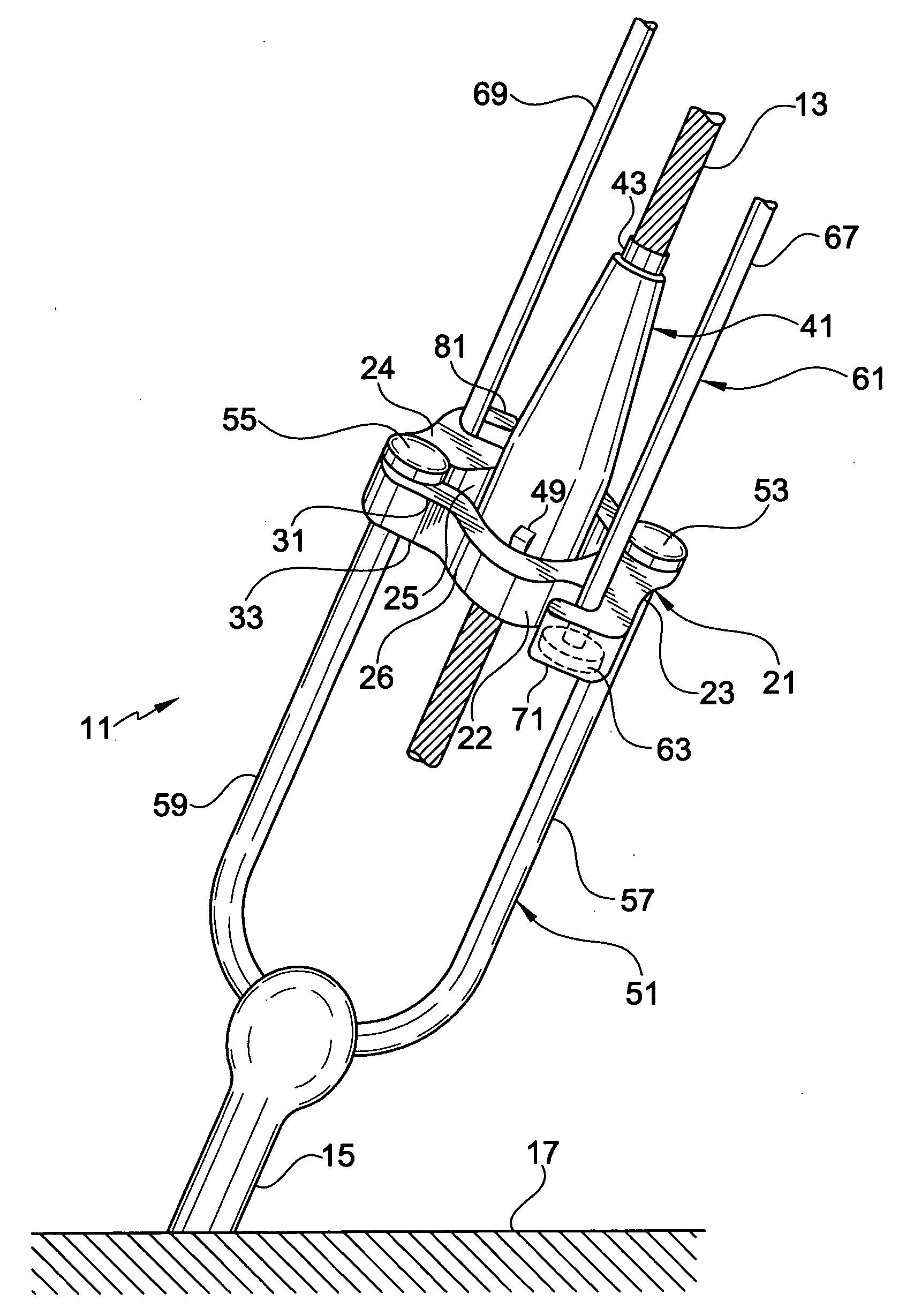
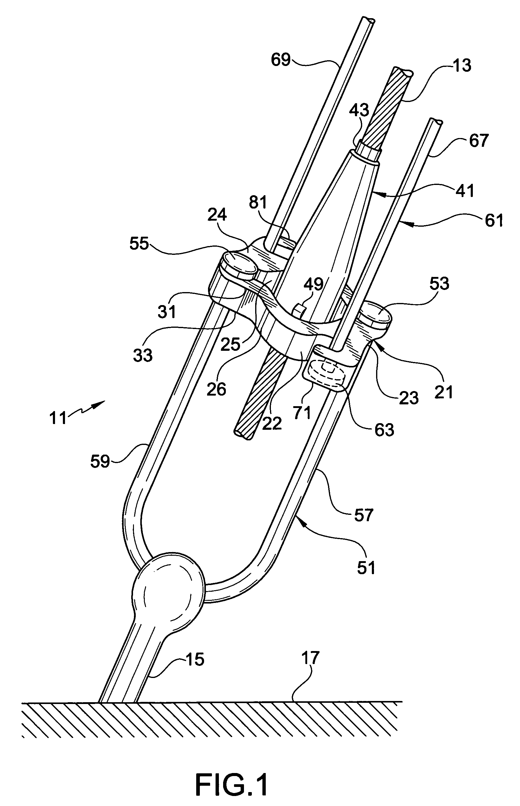
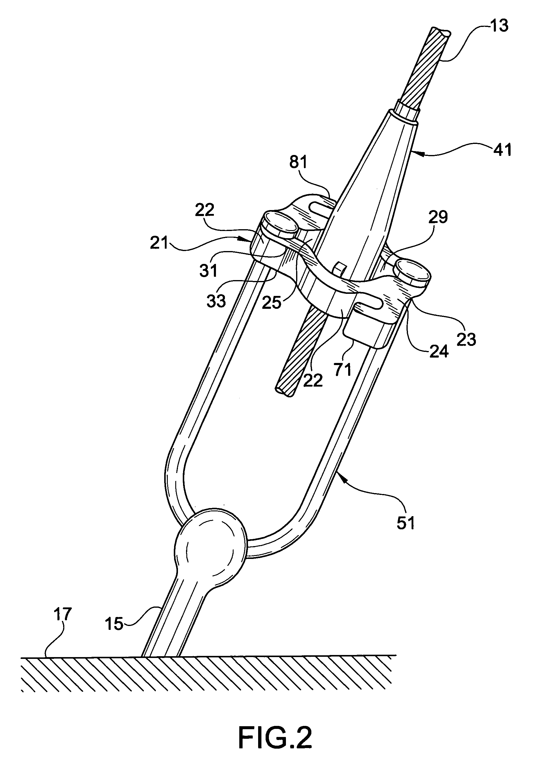
First and second hooks 71 and 81 extend from the outer surface 22 of the base 23 of the yoke 21, as shown in FIGS. 1–3. First and second hooks 71 and 81 define first and second open areas 73 and 83, respectively, for receiving ends of the second bail 61, as shown in FIGS. 1 and 3. In the present invention, first hook 71 has first and second shoulders 75 and 77 and second hook 81 has first and second shoulders 85 and 87, as shown in FIGS. 4 and 6. Each end of first and second bores 79 and 89 have shoulders at their respective ends for receiving ends of the second bail. By having first and second shoulders for each hook, either the upper or the lower surface of the yoke 21 may be facing upwardly during installation without preventing the hooks from receiving the second bail since there are shoulders at both ends of the bores to provide access from either the upper surface 24 or the lower surface 26 of the yoke. A symmetrical yoke is provided that is impossible to install incorrectly, ...

second embodiment

In a second embodiment of the present invention, as shown in FIGS. 5 and 7, first and second hooks 71 and 81 have only a first shoulder 75. Only the ends of the bores 79 and 89 proximal the lower surface 26 of the yoke 21 have a shoulder for receiving ends of the second bail 61. First shoulders 75 prevent further movement of heads 63 and 65 of second bail 61 when attached to the yoke 21. In the present invention, FIGS. 5 and 7, the yoke 21 must be installed so that the lower surface 26 is not facing upwardly, thereby providing a shoulder to prevent upward movement of the second bail 61. If the yoke of the second embodiment is installed so that the lower surface is facing upwardly, the heads of the second bail 61 would not rest on the shoulders. Therefore the shoulders would not prevent removal of the second bail as intended and the yoke must be reinstalled.

Preferably, the yoke 21, including the opening 25, slots 27 and 29 and hooks 71 and 81, is unitarily formed as a single, continu...


PUM


Abstract

A deadend assembly for anchoring a wire to a support includes a yoke having a base. An opening through the base of the yoke receives a wire receiving device and a first bail. First and second opposing hooks on the base receive a second bail. The second bail is removable to facilitate installation of additional deadend assemblies.

Description

FIELD OF THE INVENTION The present invention relates to a yoke for an automatic deadend assembly for anchoring a wire or cable to a support. More particularly, the present invention relates to a universal yoke receiving a first bail to anchor the deadend assembly and a second bail to facilitate installation of the deadend assembly. Still more particularly, the present invention relates to a method of installing a deadend assembly using a first bail to anchor the deadend assembly to a support and a second bail to facilitate installation of the deadend assembly. BACKGROUND OF THE INVENTION Terminated ends of wires, cables and the like often need to be securely fixed or anchored to a support. Securing the terminated wires to the support is particularly important for guy wires used to anchor and support large structures, such as towers and antenna masts. Deadend assemblies grip the terminated end of the wire and anchor the wire to the support. Automatic gripping units are often used wi...

Claims


Application Information

Patent Timeline
IPC IPC(8): F16G11/00F16G11/04H02G7/05
CPCF16G11/00F16G11/04H02G7/056Y10T403/4345Y10T403/4363Y10T24/3969Y10T24/135F16G11/106
Inventor GOCH, WAYMON P.
Owner HUBBELL INC
Why Eureka
Try Eureka