Wire bundle support system

a support system and wire bundle technology, applied in the direction of machines/engines, separation processes, combustion air/fuel air treatment, etc., can solve the problems of difficult to achieve a predetermined tension on the held objects, the p-clamp suffers from numerous disadvantages, and the p-clamp has very little change, so as to reduce the amount of parts in stock, the effect of reducing assembly time and installation tim

Active Publication Date: 2005-11-03
THE BOEING CO
View PDF14 Cites 34 Cited by
  • Summary
  • Abstract
  • Description
  • Claims
  • Application Information

AI Technical Summary

Benefits of technology

[0006] These and other needs are fulfilled by the support system described herein. The present support system is particularly advantageous for bundling and securing “family groups” of wires that are typically found in aircraft, boats, and other vehicles. By providing a post having a plurality of registration positions along the length thereof, the stackable riser can be positioned at a predetermined or desired height according to the registration positions, and multiple stackable risers can be arranged on a common post to organize and secure stacks or layers of wires, tubes, or other elongate objects. Advantageously, the support system is designed to receive a securing device, such as a cable tie, in conjunction with the stackable riser and / or tower member such that elongate objects of various diameters can be secured to the support system. As such, the support system acts as a “universal” system that greatly reduces part inventory, assembly time, and installation time.

Problems solved by technology

Unfortunately, P-clamps suffer from numerous disadvantages.
Also, it is difficult to achieve a predetermined tension on the held objects, and thus it is sometimes necessary to use additional fillers or spacers to encircle the objects to provide consistent compressive forces.
The P-clamp has changed very little over the years, which is surprising considering the various problems associated with use.
Most assemblers agree that the installation of these clamps is difficult because of their stiffness.
Furthermore, the use of commercially available P-clamps on electrical cables is complicated by the fact that electrical cable diameter dimensions are not tightly controlled and that cables have soft, irregular cross-sections which can be damaged by excessive force caused by securing with a P-clamp.
This creates a huge inventory of parts and drawings.
Unfortunately, presently available mounts for tie straps require that both sides of the mount be accessible for entry and exit of the strap.

Method used


Image

  • Wire bundle support system
  • Wire bundle support system
  • Wire bundle support system

Examples


Embodiment Construction

[0020] The present inventions now will be described more fully hereinafter with reference to the accompanying drawings, in which some, but not all embodiments of the invention are shown. Indeed, these inventions may be embodied in many different forms and should not be construed as limited to the embodiments set forth herein; rather, these embodiments are provided so that this disclosure will satisfy applicable legal requirements. Like numbers refer to like elements throughout.

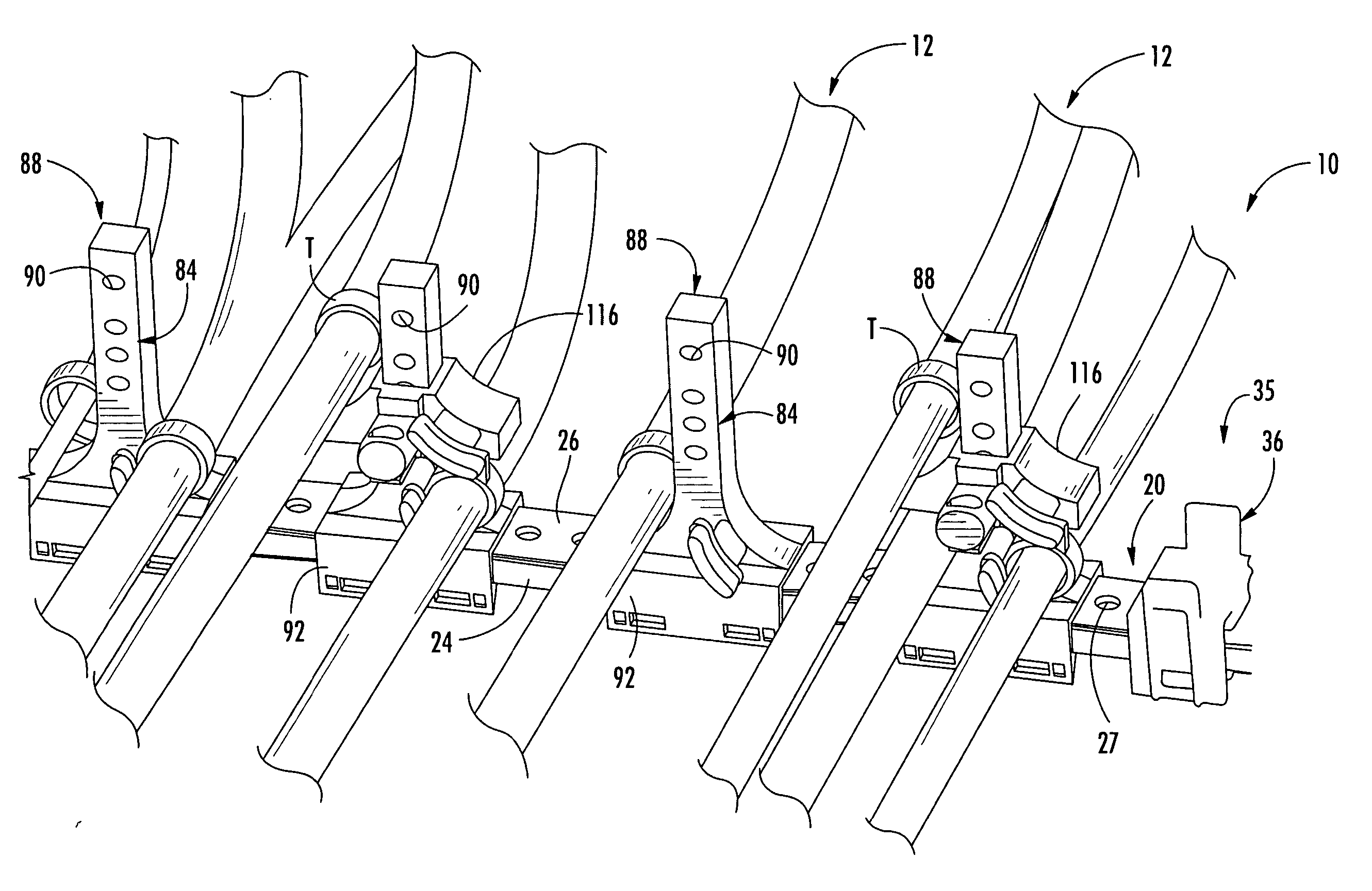
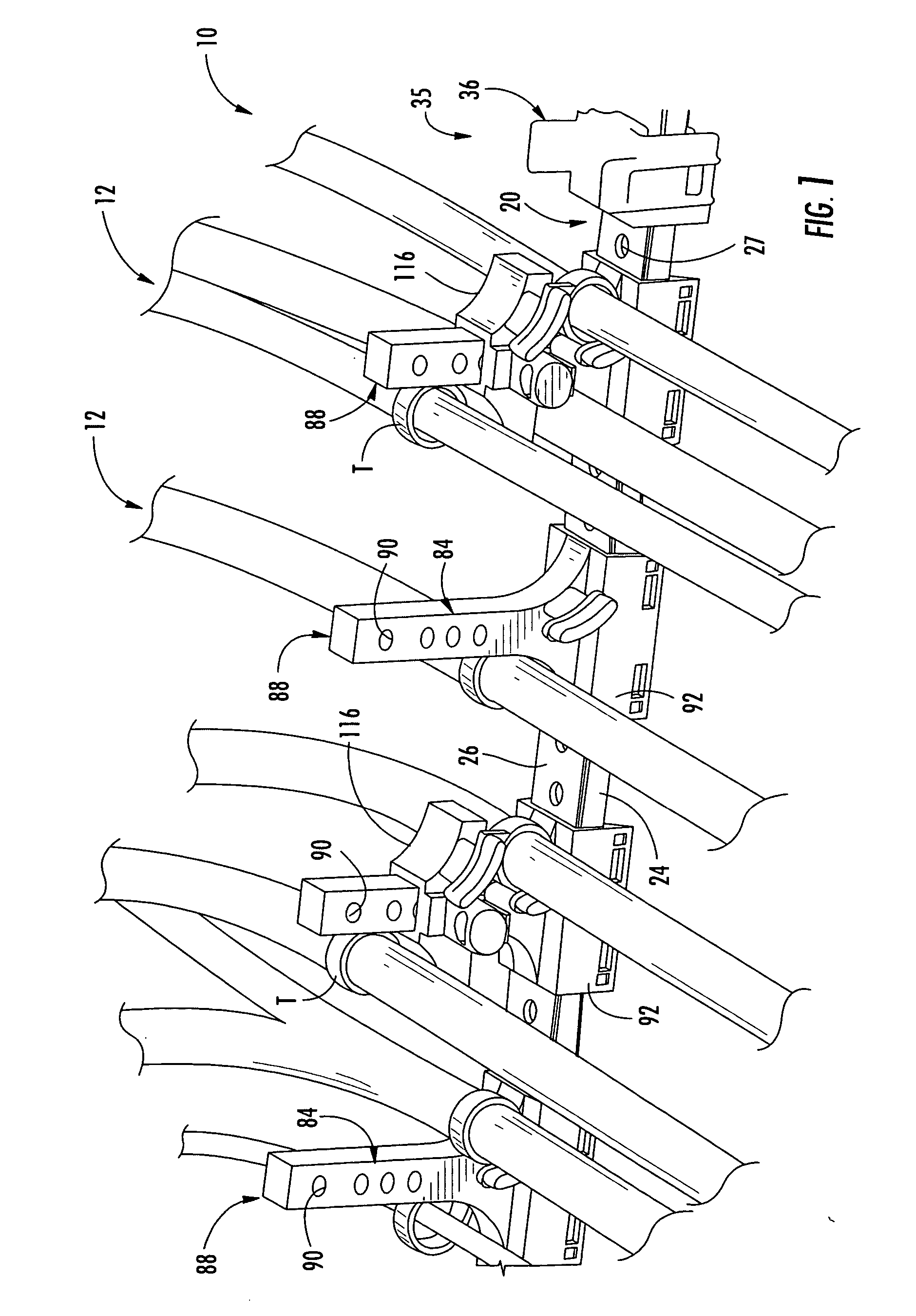
[0021] Turning now to the Figures, FIG. 1 shows a support system 10 for engaging and securing a plurality of elongate objects 12. The elongate objects 12 may be different types of wires, cables, pipes, conduits, or any other elongate objects, tubular or of other cross section, that extend over an elongate path, such as along the raceways, main runs, or in the crown of an aircraft or other vehicle. The support system 10 may also be utilized in non-vehicular settings, such as in office ceilings, crawl spaces in...


PUM

PropertyMeasurementUnit
lengthaaaaaaaaaa
distanceaaaaaaaaaa
lengthaaaaaaaaaa

Abstract

A support system for an elongate object comprising an elongate support bar, a tower member, and a stackable riser for securing the elongate object to the tower member.

Description

BACKGROUND [0001] The present invention relates to support systems. More specifically, the present invention relates to a support system for securing elongate objects, such as electrical wires, tubes, and hoses. [0002] Many types of mounting devices have been developed over the years for holding one or more elongate objects to a support. One of the more popular devices for use in vehicles, including automobiles and airplanes, has been the “P” clamp. The P-clamp includes a metal strap formed into a generally circular portion with each end of the strap terminating in a flat foot portion. After elongate objects are encircled by the circular portion, the feet are overlapped until apertures in the feet are aligned to receive a threaded fastener. Unfortunately, P-clamps suffer from numerous disadvantages. Foremost, P-clamps are generally not adjustable so that when they are used in an environment where different sizes of bundles have to be accommodated, a large inventory of different size...

Claims


Application Information

Patent Timeline
Patent Type & Authority Applications(United States)
IPC IPC(8): B01D47/00F02M29/04F16L3/08F16L3/23F16L3/24
CPCB64C1/406Y02T50/46F16L3/24F16L3/23F16L3/243Y02T50/40
Inventor BALDERAMA, MARKHOLUM, THOMAS A.LAY, LENNY E.
Owner THE BOEING CO
Why Eureka
Try Eureka