Snap-on multi-planar and mono-planar receiver assemblies having integral and multi-part multipurpose positioners for pivoting and non-pivoting retainers

a receiver and monoplanar technology, applied in the field of pivoting bone anchors, can solve problems such as difficult or impossible to do, and achieve the effect of facilitating the engagement of retainers

Active Publication Date: 2017-11-23
JACKSON ROGER P
View PDF6 Cites 29 Cited by
  • Summary
  • Abstract
  • Description
  • Claims
  • Application Information

AI Technical Summary

Benefits of technology

[0100]Aspects of the present disclosure may also involve a receiver assembly for connecting to a capture structure of a proximal end of a bone anchoring member to form a bone anchor assembly configured to anchor a rod to patient bone. In one embodiment, the receiver assembly includes a receiver body, a retainer and a positioner. The retainer resides within the receiver body and is configured to engage in a locking manner with the capture structure via the proximal end of the bone anchor member being inserted into the receiver body. The positioner resides in the receiver body and is configured to maintain an orientation of the retainer within the receiver body that facilitates the retainer engaging in the locking manner with the capture structure. The positioner is also configured to allow the retainer to change orientation within the receiver body when the retainer is engaged in the locking manner with the capture structure.
[0101]In one embodiment, the positioner is also configured to allow the retainer to change orientation relative to the positioner when the retainer is engaged in the locking manner with the capture structure. The positioner may orient the retainer such that a central opening of the retainer is generally coaxially aligned with a distal opening in a distal end of the receiver body. The positioner may limit the proximal displacement of the retainer within the inner volume.

Problems solved by technology

This is sometimes very difficult or impossible to do.

Method used


Image

  • Snap-on multi-planar and mono-planar receiver assemblies having integral and multi-part multipurpose positioners for pivoting and non-pivoting retainers
  • Snap-on multi-planar and mono-planar receiver assemblies having integral and multi-part multipurpose positioners for pivoting and non-pivoting retainers
  • Snap-on multi-planar and mono-planar receiver assemblies having integral and multi-part multipurpose positioners for pivoting and non-pivoting retainers

Examples


Embodiment Construction

[0258]As required, detailed embodiments of the present disclosure are disclosed herein; however, it is to be understood that the disclosed embodiments are merely exemplary of the disclosure, which may be embodied in various forms. Therefore, specific structural and functional details disclosed herein are not to be interpreted as limiting, but merely as a basis for the claims and as a representative basis for teaching one skilled in the art to variously employ the present disclosure in virtually any appropriately detailed structure.

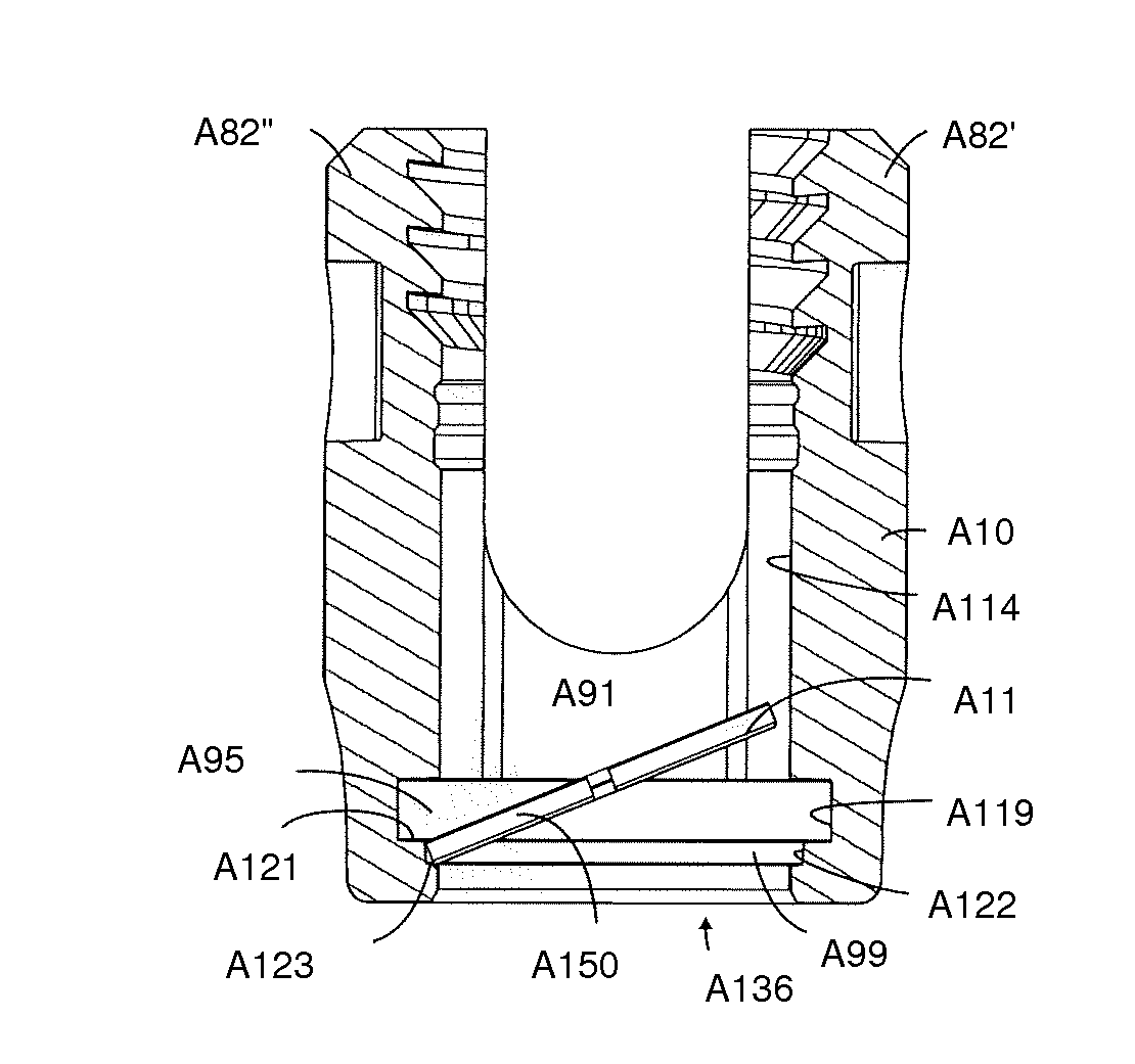
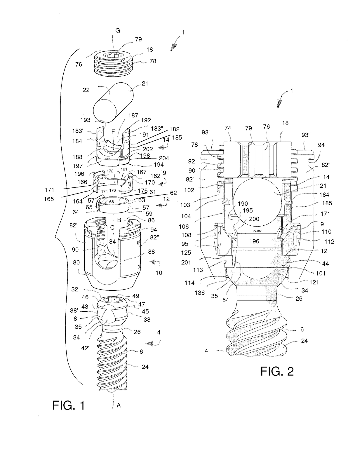
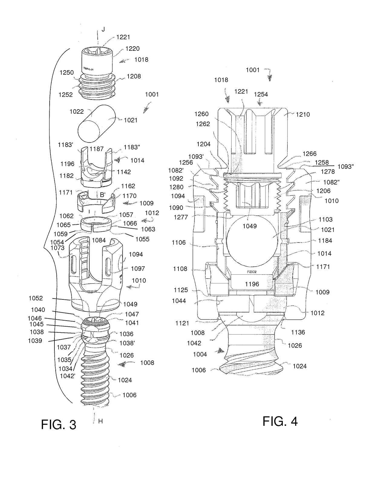
[0259]With reference to FIGS. 1-2 the reference number 1 generally represents an embodiment of a multi-planar, multi-axial, or polyaxial bone screw apparatus or assembly according to the present disclosure. While the illustrated anchor 1 is generally a polyaxial bone screw, it is foreseen that the disclosure could be utilized with other types of spinal implants that utilize pressure inserts, such as polyaxial bone hooks or clamps, for example. The illustra...


PUM


Abstract

A receiver subassembly adapted to couple with a universal shank to form a bone anchor assembly. The universal shank having an integral upper capture structure with opposed spaced apart flat side surfaces. The receiver subassembly including a receiver including a distal opening for bottom loading of the capture structure of the universal shank there-through. The receiver supporting a retainer and a positioner within the receiver. The positioner supporting a position of the retainer within the receiver. The retainer configured to couple with the capture structure when the capture structure extends at least partially through the distal opening.

Description

CROSS-REFERENCE TO RELATED APPLICATIONS[0001]This Patent Cooperation Treaty (PCT) patent application claims priority to and the benefit of U.S. Provisional Patent Application No. 62 / 194,955, filed Jul. 21, 2015; titled “BONE ANCHOR ASSEMBLIES HAVING NON-PIVOTING RETAINERS AND PIVOTING SHANKS, SOME WITH PIVOTING RETAINERS,” and is hereby incorporated by reference in its entirety into the present application.[0002]This Patent Cooperation Treaty (PCT) patent application claims priority to and the benefit of U.S. Provisional Patent Application No. 62 / 137,713, filed Mar. 24, 2015; titled “BONE ANCHOR HAVING A SNAP-FIT ASSEMBLY COUPLING AN ANCHOR HEAD TO AN ANCHOR SHANK,” and is hereby incorporated by reference in its entirety into the present application.[0003]This Patent Cooperation Treaty (PCT) patent application claims priority to and the benefit of U.S. Provisional Patent Application No. 62 / 137,707, filed Mar. 24, 2015; titled “BONE ANCHOR HAVING A SNAP-FIT ASSEMBLY COUPLING AN ANCHO...

Claims


Application Information

Patent Timeline
Patent Type & Authority Applications(United States)
IPC IPC(8): A61B17/70A61B17/86
CPCA61B17/864A61B17/7037A61B17/8605A61B17/7035A61B17/702A61B2090/037A61B17/7038A61B17/863
Inventor JACKSON, ROGER P.SURBER, JAMES L.
Owner JACKSON ROGER P
Why Eureka
Try Eureka