
Breather filter for sealed spring brake actuators

a spring brake actuator and filter filter technology, applied in the direction of brake cylinders, braking systems, braking components, etc., can solve the problems of affecting the service life of the spring brake, requiring extra components and complex machining of the components, external filters that require additional space, machining and assembly effort, etc., and achieves the effect of satisfying the filtering of contaminants

Inactive Publication Date: 2005-04-05
HALDEX BRAKE
View PDF12 Cites 6 Cited by
  • Summary
  • Abstract
  • Description
  • Claims
  • Application Information

AI Technical Summary

Benefits of technology

Another object of the present invention is to provide a brake actuator assembly having the above characteristics and which filters out unwanted contaminants from entering the actuator brake housing.
Still another object of the present invention is to provide a brake actuator assembly having the above characteristics and which does not require that additional holes be created in the housing.
Yet a further object of the present invention is to provide a brake actuator assembly having the above characteristics and which achieves satisfactory filtering of contaminants.

Problems solved by technology

Because the force generated by the compression spring is quite large, it can be dangerous to service the spring brake if the spring has not been properly restrained.
However, this allows dirt, salt, moisture and other unwanted material and contaminants from the environment outside the brake chamber to enter that chamber through the ports.
Some prior art brake designs have used complex arrangements of valves and fluid conduits to permit fluid flow to the spring brake chamber from other chambers in the brake actuator assembly.
These arrangements require extra components and complex machining of the components.
However, external filters require additional space, components, machining and assembly effort.
However, this reference does not disclose any type of filter or vent system at all.
All of the prior art references listed above suffer from a number of disadvantages, including the fact that complex filter designs are employed, that additional holes are required to be created in the housing, and / or that unsatisfactory filtering of contaminants is achieved.

Method used


Image

  • Breather filter for sealed spring brake actuators
  • Breather filter for sealed spring brake actuators
  • Breather filter for sealed spring brake actuators

Examples


Embodiment Construction

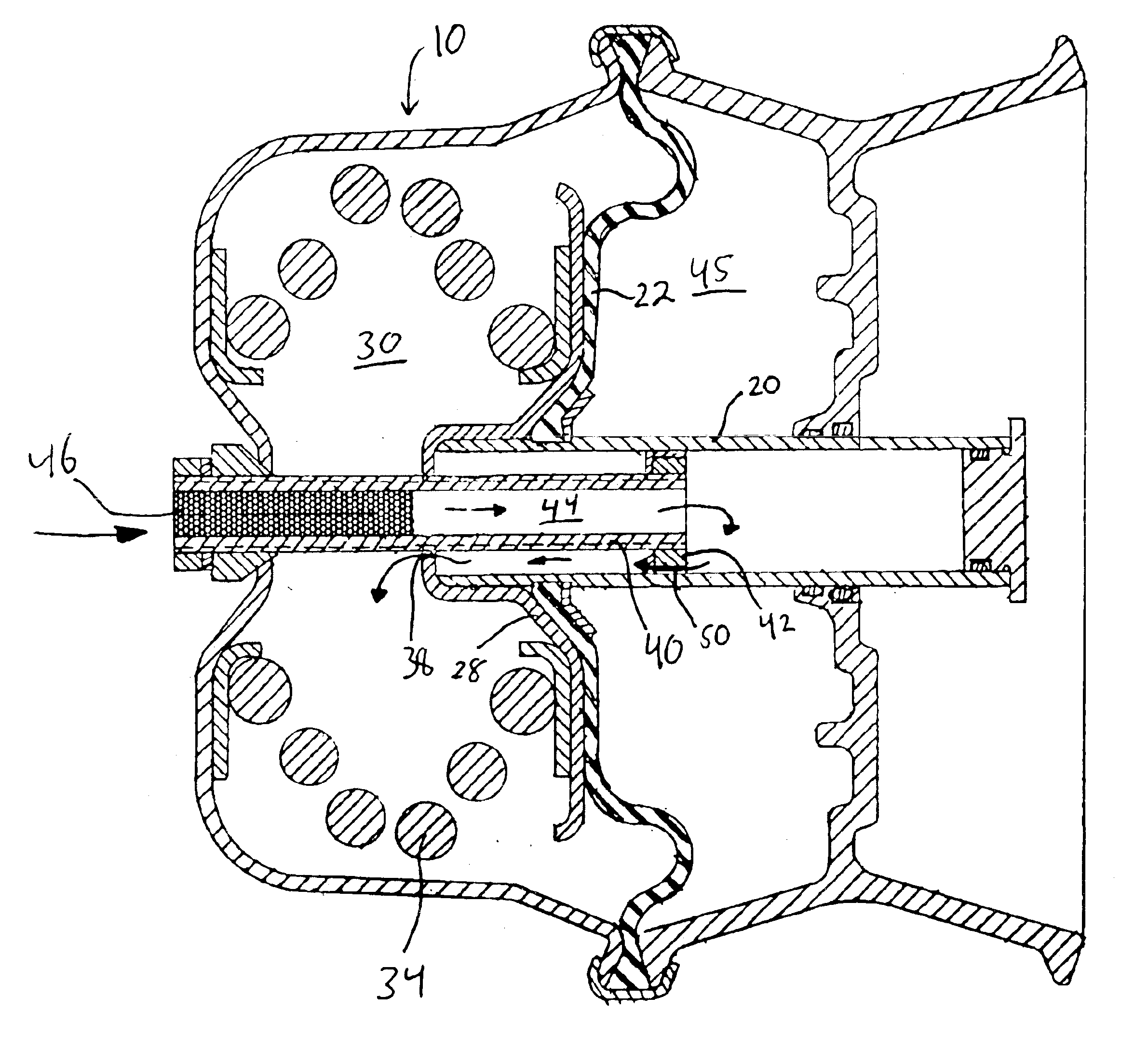
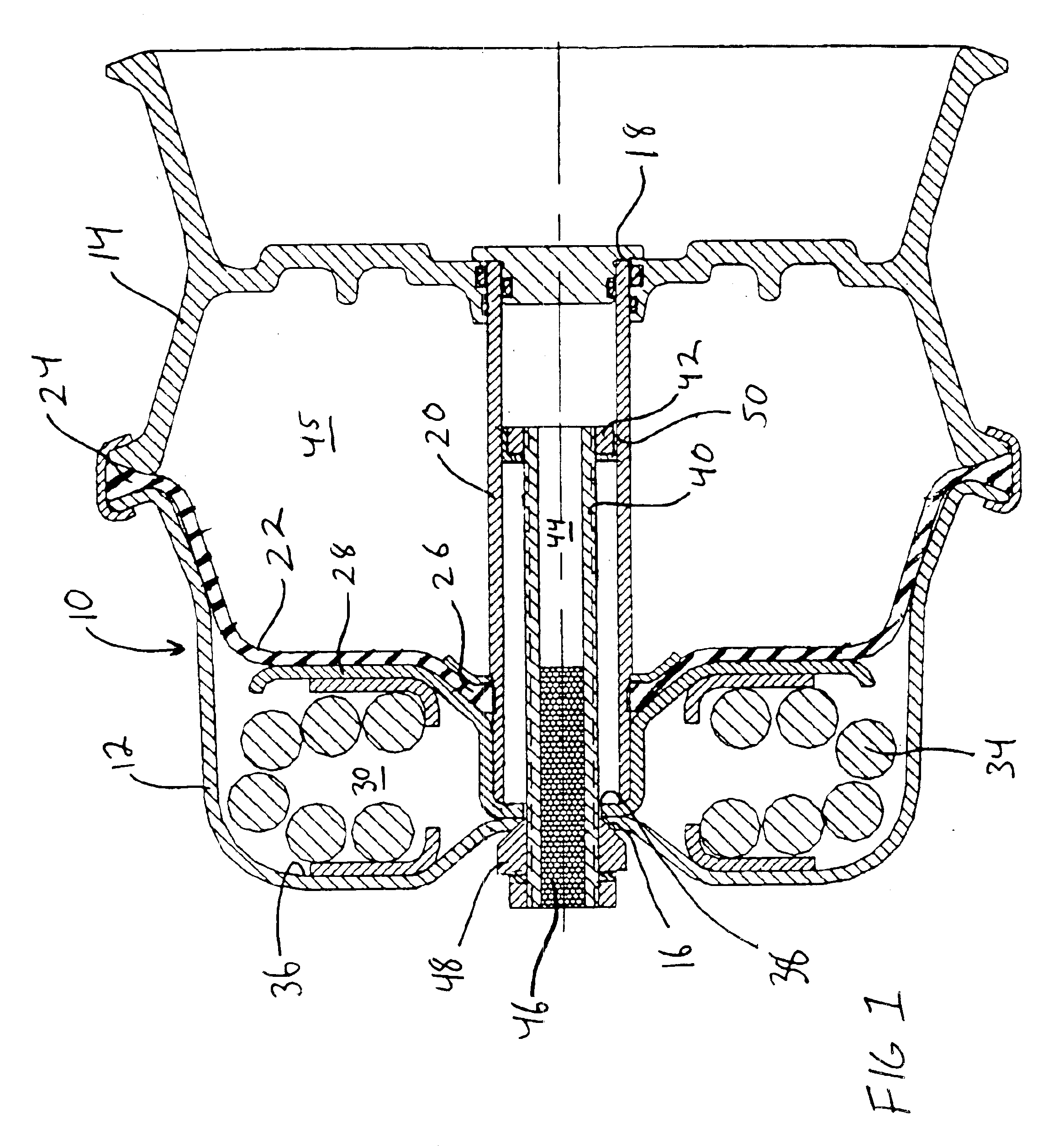
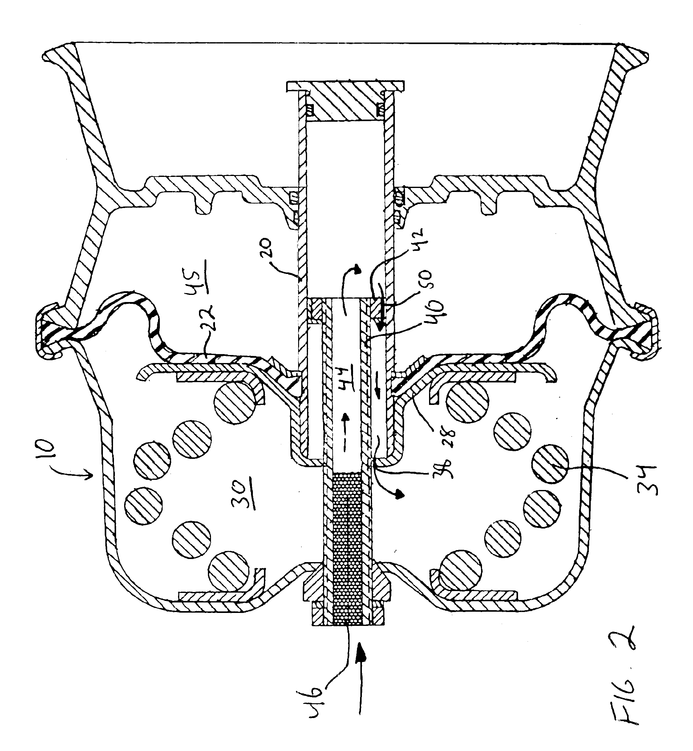
An exemplary embodiment of a brake actuator assembly in accordance with the invention is shown in FIG. 1. The brake actuator assembly includes a brake housing 10, which is formed of two portions, a spring break chamber or first proximal portion 12 and a second distal portion 14. The first proximal portion defines an aperture 16 in the proximal end of the housing 10 while the second distal portion defines an aperture 18 in the distal end of the housing 10. A sleeve 20 is slideably located at least partially within housing 10 and can move reciprocally from a retracted position within the housing to extended position outside the housing. A diaphragm 22 is attached between the sleeve 20 and the housing 10. In the disclosed embodiment, the diaphragm's outer periphery 24 is attached to the housing 10 where the first housing portion 12 and the second housing portion 14 meet. In the embodiment shown in FIG. 1, the diaphragm's inner periphery 26 is attached near the proximal end of sleeve 20...


PUM


Abstract

A brake actuator assembly includes a housing defining a spring chamber. A spring is disposed in the spring chamber, the spring being biased toward an extended position and movable against the bias toward a caged position. A release assembly is provided for selectively moving and retaining the spring against the bias toward the caged position, the release assembly comprising a hollow release bolt having a fluid passage passing therethrough by which fluid passage the spring chamber is in fluid communication with an environment surrounding the housing. A filter is disposed within the fluid passage in the hollow release bolt for filtering fluid passing through the fluid passage.

Description

FIELD OF THE INVENTIONThe present invention relates generally to spring brake actuators for vehicles and particularly diaphragm- or piston-style spring brake actuators.BACKGROUND OF THE INVENTIONAn air brake system for a vehicle such as a bus, truck or the like typically includes a brake actuator assembly which is actuated by means of an actuator assembly operated by the selective application of a fluid such as compressed air. Conventional air brake actuators typically have both a service brake actuator for actuating the brakes under normal driving conditions by the application of compressed air and an emergency or spring brake actuator which causes actuation of the brakes when air pressure has been released. The spring brake actuator can be used as a parking brake or emergency brake in the event that the air pressure system fails. The spring brake actuator includes a compression spring which forces application of the brake when fluid or air pressure is either released or lost. Typi...

Claims


Application Information

Patent Timeline
Patent Type & Authority Patents(United States)
IPC IPC(8): B60T17/00B60T17/08
CPCB60T17/08
Inventor FISHER, ALBERT D.
Owner HALDEX BRAKE
Learn More