Optical touch device

a touch device and optical technology, applied in the field of optical touch devices, can solve the problems of increasing manufacturing costs, difficult assembly, and the inability of conventional optical touch devices without substantial frames to precisely determine the touch point, so as to reduce manufacturing costs and accurately determine the touch object

Active Publication Date: 2013-05-02
WISTRON CORP
View PDF13 Cites 0 Cited by
  • Summary
  • Abstract
  • Description
  • Claims
  • Application Information

AI Technical Summary

Benefits of technology

[0018]The optical touch device of the present invention utilizes the optical virtual frame as a background when the object is located within the coordinate detecting area, and there is no need to utilize a substantial reflective frame or a substantial non-reflective frame. It can achieve a purpose of filtering out the object not located within the coordinate detecting area. As a result, it can overcome the assembly difficulty, reduce manufacturing cost, and have the accurate determination of the touch object with image processing.

Problems solved by technology

However, the substantial frame needs to be on the same plane with the sensor, resulting in difficulty in assembly and increasing manufacturing cost.
But the conventional optical touch device without the substantial frame can not determine a touch point precisely due to the interference outside the coordinate detecting area.
As a result, design of an optical touch device for effectively decreasing assembly difficulties and cost and for increasing determining accuracy is an important issue of the touch technology.

Method used


Image

  • Optical touch device
  • Optical touch device
  • Optical touch device

Examples


Embodiment Construction

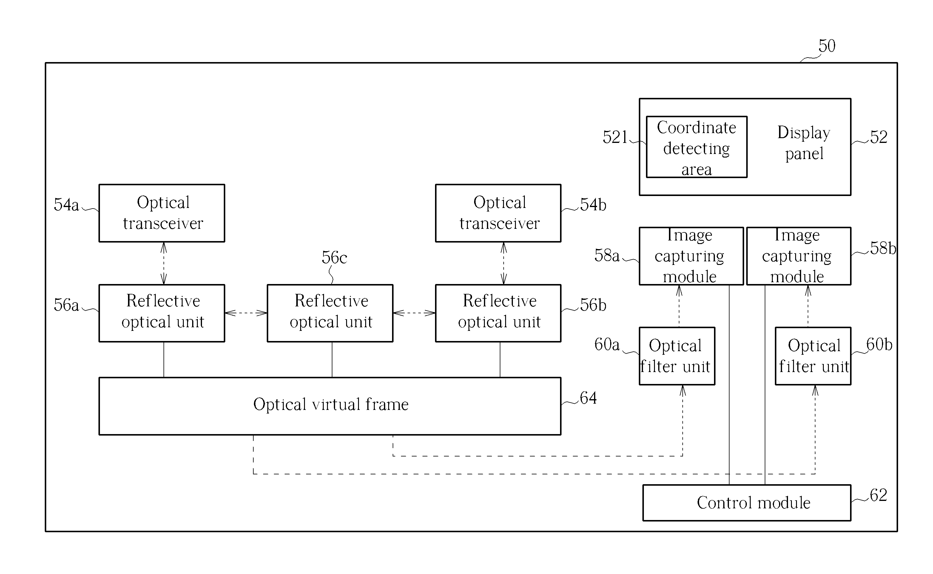
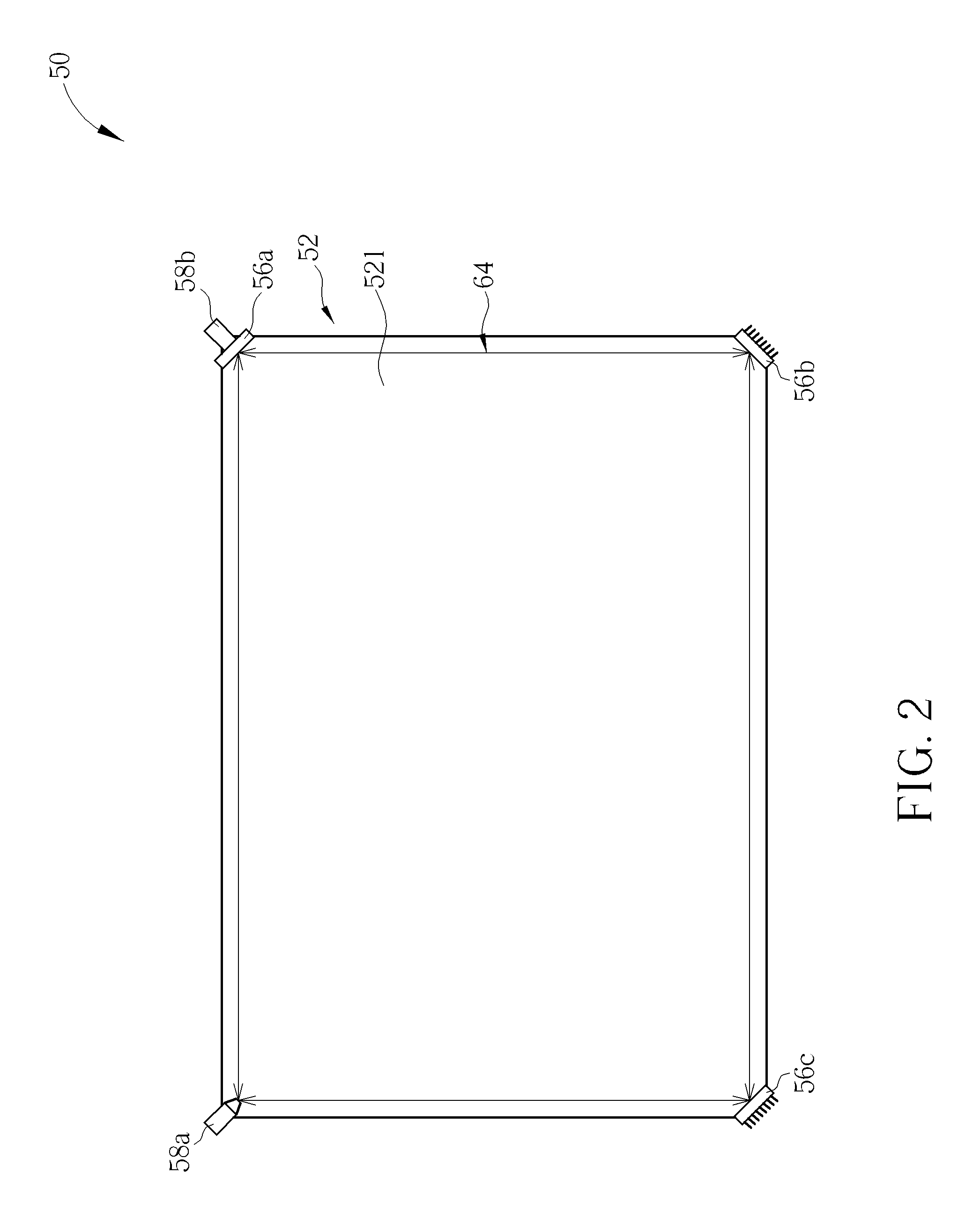
[0024]Please refer to FIG. 1 to FIG. 5. FIG. 1 is a functional block diagram of an optical touch device 50 according to an embodiment of the present invention. FIG. 2 is a front view of the optical touch device 50 according to the embodiment of the present invention. FIG. 3 to FIG. 5 are respectively side views in different portions of the optical touch device 50 according to the embodiment of the present invention. The optical touch device 50 includes a display panel 52, two optical transceivers 54a, 54b, three reflective optical units 56a, 56b, 56c, two image capturing modules 58a, 58b, two optical filter units 60a, 60b, and a control module 62. The display panel 52 can be a touch panel whereon a coordinate detecting area 521 is formed. The two optical transceivers 54a, 54b are disposed on a corner of the display panel 52 for transceiving a plurality of beams travelling in parallel and in opposite directions so as to form an optical virtual frame 64. The plurality of beams travell...


PUM


Abstract

An optical touch device includes a display panel whereon a coordinate detecting area is formed, at least one optical transceiver disposed on a corner of the display panel for transceiving a plurality of beams travelling along an edge of the coordinate detecting area so as to form an optical virtual frame, at least one image capturing module disposed on a corner of the display panel for capturing surroundings of an object, and a control module coupled to the at least one image capturing module for determining whether to calculate a coordinate value of the object according to whether the object blocks the optical virtual frame by the captured surroundings of the object.

Description

BACKGROUND OF THE INVENTION[0001]1. Field of the Invention[0002]The present invention relates to an optical touch device, and more specifically, to an optical touch device without using a reflective frame or a non-reflective frame.[0003]2. Description of the Prior Art[0004]In the modern consumer electronic products, a portable electronic product such as a personal digital assistant, a smart phone or a mobile phone is equipped with a touch control device as an interface for data transmission. Since consumer electronic products have become lighter, thinner, shorter and smaller, there is no space on these products for containing a conventional input device, such as a mouse, a keyboard and so on. Furthermore, with development of tablet computers focusing on humanity design, a display with the touch control device has gradually become one of the key components in various electronic products. A variety of touch control technologies, such as a resistive type, a capacitive type, an ultrason...

Claims


Application Information

Patent Timeline
Patent Type & Authority Applications(United States)
IPC IPC(8): G06F3/042
CPCG06F3/0421G06F3/042
Inventor CHOU, CHIA-TE
Owner WISTRON CORP
Why Eureka
Try Eureka