Ground connector and method of mounting it

a ground connector and connector technology, applied in the direction of coupling device connection, connection contact member material, coupling protective earth/shielding arrangement, etc., can solve problems such as difficulty in alignment, and achieve the effect of improving the mounting efficiency of ground connectors, facilitating operation, and sufficient rigidity

Inactive Publication Date: 2005-04-05
SUMITOMO WIRING SYST LTD
View PDF12 Cites 22 Cited by
  • Summary
  • Abstract
  • Description
  • Claims
  • Application Information

AI Technical Summary

Benefits of technology

The grounding portion can be positioned quickly and precisely before being fastened by the screw. As a result, the mounting efficiency of the ground connector is improved.
Engaged parts of the positioning portion and the engaging portion preferably have cross sections that will quickly and precisely position the grounding portion.
Engaged parts of the positioning portion and the engaging portion preferably have sufficient rigidity to prevent the housing from turning as the grounding portion is fastened by the screw. Thus, the housing need not be pressed to prevent turning, and the operation is easier.

Problems solved by technology

This alignment may be difficult in some situations.

Method used


Image

  • Ground connector and method of mounting it
  • Ground connector and method of mounting it
  • Ground connector and method of mounting it

Examples


Embodiment Construction

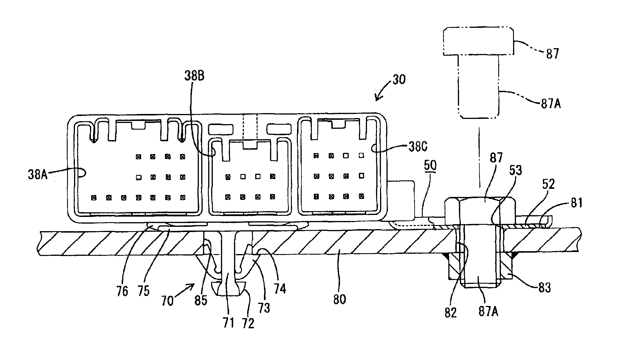
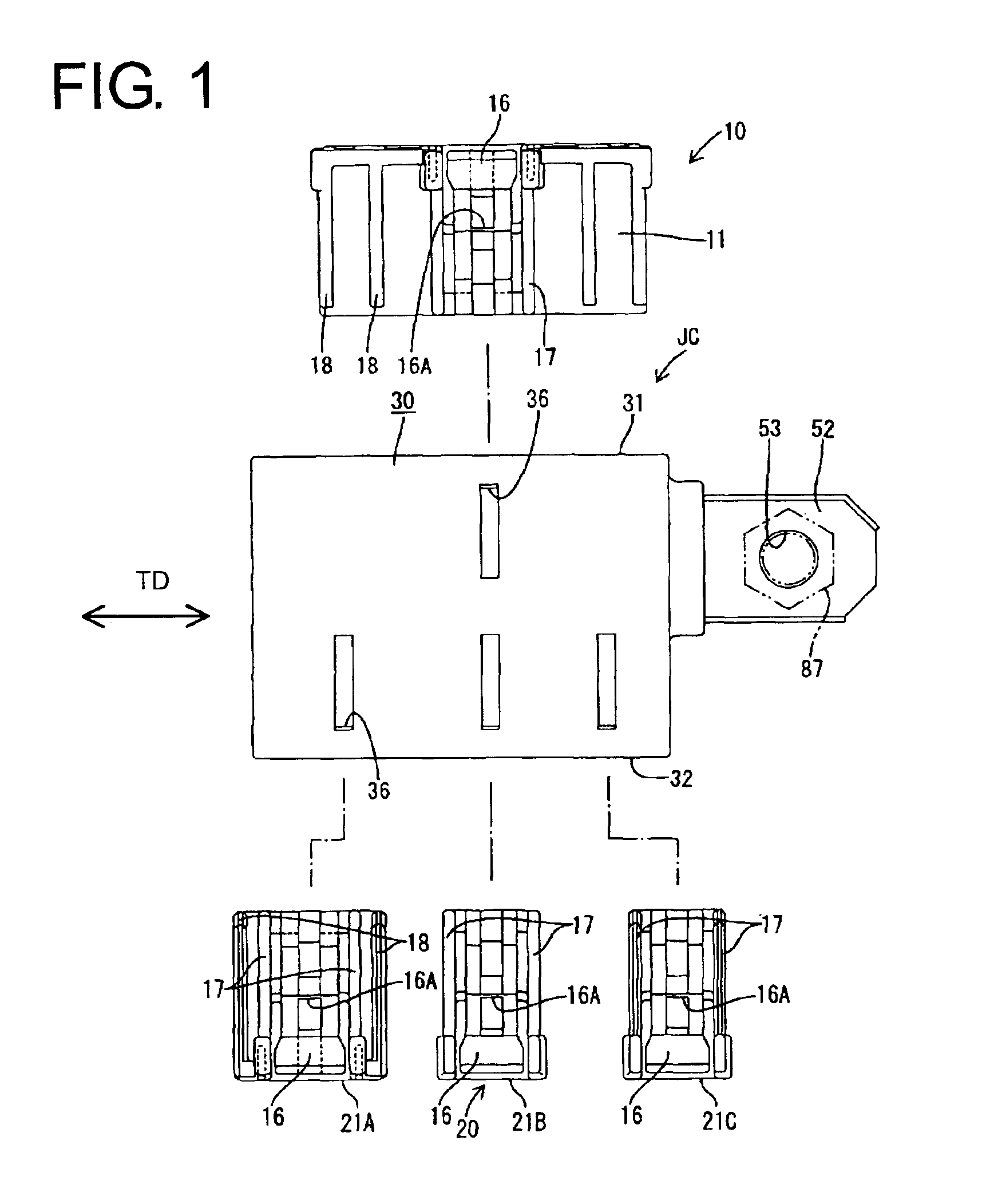
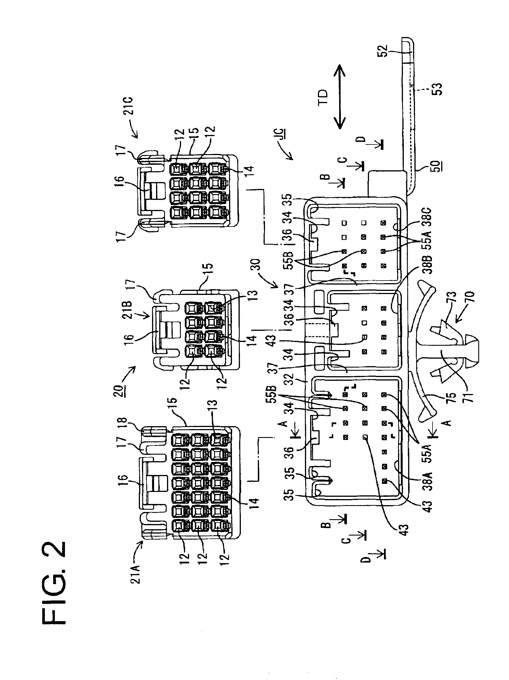
A joint connector according to the invention is identified by JC in FIG. 1. A power-supply side connector 10 and electric-part side connectors 20 are connected with substantially opposite surfaces of the joint connector JC. The joint connector JC is mountable on a metal panel 80 as a grounding member.

The power-supply side connector 10 has a power-supply side housing 11 made e.g. of a synthetic resin. The power-supply side housing 11 is a block with a wide rectangular cross section, as shown in FIGS. 3 and 5. Cavities 12 extend forward and backward at each of two levels in the power-supply side housing 11. A terminal insertion opening 13 is formed in the front mating side of each cavity 12.

Female terminals 26 secured to ends of wires 25 are inserted into the respective cavities 12 from behind (from right in FIG. 5), and are locked by locks 14 at bottom surfaces of the cavities 12 and by a retainer 15. Some of the cavities are empty and have no female terminal 26.

A lock arm 16 is at a...


PUM


Abstract

A joint connector (JC) has a ground terminal (50) mounted in a housing (30) so that a grounding plate (52) projects outside. The grounding plate (52) is fastened to a metal panel (80) by a nut (83) and bolt (87). A mount hole (85) of rectangular cross section is formed at a specified distance in a specified direction from the nut (83). A clip (70) is formed on the bottom of the housing (30) so that the positional relationship of the clip (70) and an insertion hole (53) of the grounding plate (52) corresponds to that of the mount hole (85) of the nut (83) of the metal panel (80). The housing (30) is mounted on the metal panel (80) by inserting the clip (70) into the mount hole (85). Thus, the insertion hole (53) of the grounding plate (52) is at a position aligned with the nut (83).

Description

BACKGROUND OF THE INVENTION1. Field of the InventionThe invention relates to a ground connector.2. Description of the Related ArtJapanese Unexamined Utility Model Publication No. H07-8976 shows a ground joint connector with a housing. The housing has a connecting portion for receiving a mating connector and mating terminals. A ground terminal with terminal pieces projecting therefrom is mounted so that the respective terminal pieces project into the connecting portion and so that a grounding portion projects outside. The grounding portion is fixed to a grounding member, such as a metal panel. The mating terminals are connected with ends of wires for grounding. The mating connector that accommodates the mating terminals is fit to the connecting portion so that the wires can be grounded collectively.An insertion hole is formed in the grounding portion, and a nut is secured to the metal panel. The nut is screwed down on a bolt inserted through the insertion hole to fasten the nut to th...

Claims


Application Information

Patent Timeline
Patent Type & Authority Patents(United States)
IPC IPC(8): H01R4/64H01R13/73H01R13/46H01R31/02H01R31/08H02G3/08
CPCH01R4/64H01R13/73
Inventor FUJII, MASAYASUSAKURAI, TOSHIKAZUFUKATSU, YUKIHIRO
Owner SUMITOMO WIRING SYST LTD
Why Eureka
Try Eureka