
Method for fluidisation of pulp flow in the headbox of a paper machine or such and control equipment used in the fluidisation

a technology of fluidisation and pulp flow, which is applied in the direction of machine wet end, papermaking, textiles and paper, etc., can solve the problems of insufficient fluidisation of flow, insufficient yield of boundary-layer turbulence, and more disadvantageous floc structure, so as to achieve the effect of increasing the consistency of web formation, generating more turbulence, and improving paper quality

Inactive Publication Date: 2005-04-05
VALMET TECH INC
View PDF7 Cites 2 Cited by
  • Summary
  • Abstract
  • Description
  • Claims
  • Application Information

AI Technical Summary

Benefits of technology

In the headbox structure according to the invention, it has been found that by increasing pipe-specific flows of the headbox's turbulence generator the paper quality is improved and the web formation consistency can be increased. This is possible by generating more turbulence in the fluidiser and thus bringing about a more complete fluidisation than with traditional headbox solutions. The harmful effects of the raised turbulence level are eliminated by limiting the scale of vortex size of the generated turbulence.

Problems solved by technology

Due to the restrictions may be the working range it is very difficult to carry out such changes in the process, which aim at increasing the production and at improving the quality of the product.
However, the most significant fluidisation-promoting effect of the lamellas relates to their tip turbulences.
Although these turbulences are advantageous for the fluidisation, they will cause coherent flow structures in the flow, which will weaken slowly, but which can be seen even in the produced paper.
In practice, the added friction surface brought about by lamellas and the resulting increased yield of boundary-layer turbulence are not sufficient to fluidise the flow.
An incomplete (cautious) fluidisation carried out in many stages leads to a more disadvantageous floc structure than fluidisation carried out successfully in one go and based on a controlled residence time.

Method used


Image

  • Method for fluidisation of pulp flow in the headbox of a paper machine or such and control equipment used in the fluidisation
  • Method for fluidisation of pulp flow in the headbox of a paper machine or such and control equipment used in the fluidisation
  • Method for fluidisation of pulp flow in the headbox of a paper machine or such and control equipment used in the fluidisation

Examples


Embodiment Construction

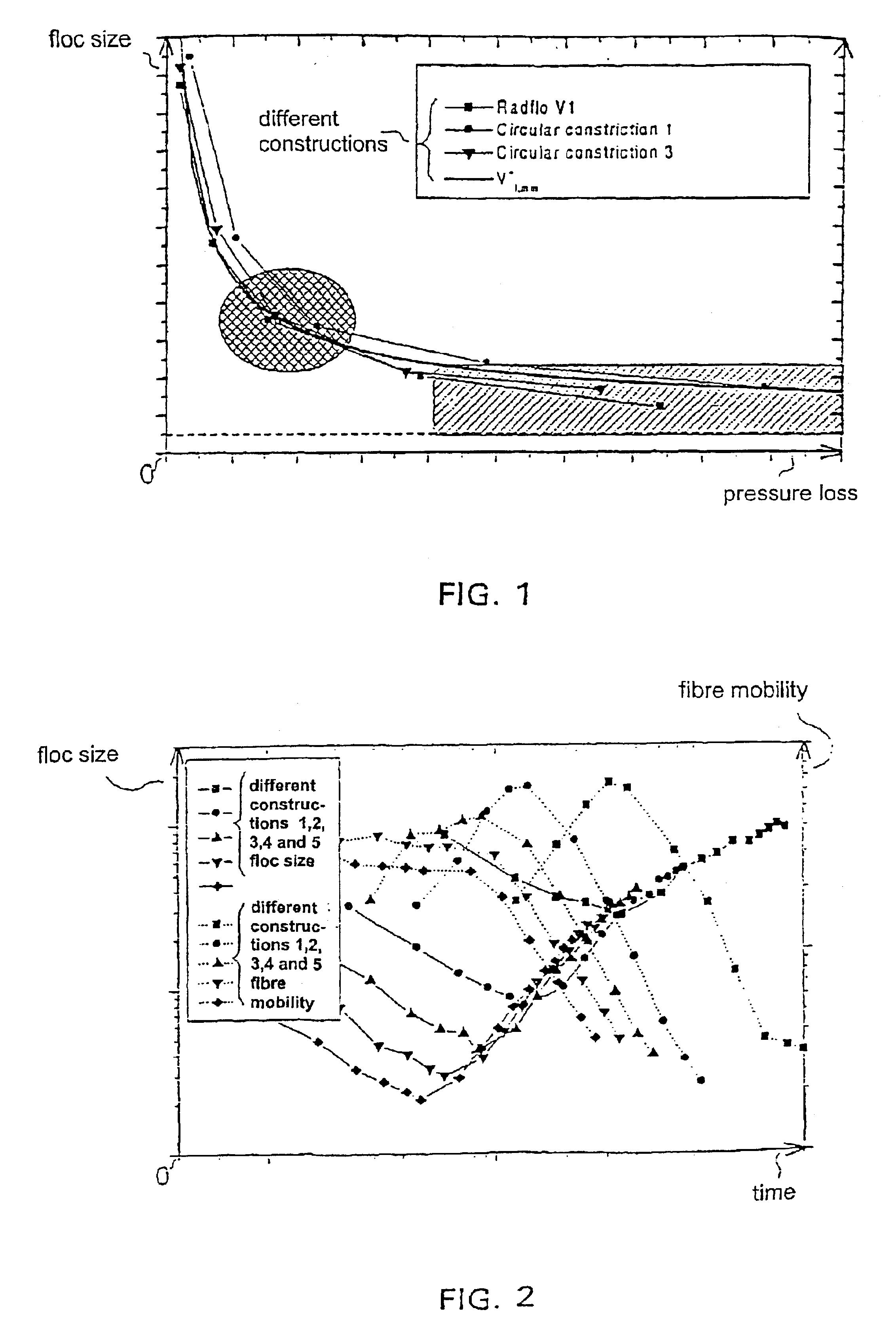
FIG. 1 shows fluidisation (an oval) brought about by the fluidiser of a conventional traditional headbox and the working range (a rectangle) of the headbox according to the invention. The fluidisation element of the headbox according to the invention, e.g. in a tubular turbulence generator, is dimensioned so that the lower limit of its working range corresponds by and large with the optimum of the pressure loss-minimum floc size curve (slope=−1).

Since the minimum floc size is reduced logarithmically as the loss power (the flow rate) increases, almost the same fluidisation level is achieved with flow rates exceeding the dimensioning point corresponding with the above-mentioned optimum. However, due to the higher flow rate, a shorter residence time than before hereby results and thus a better fluidisation level is achieved in the outflow from the headbox. The maximum of the flow rate range is formed by the time needed in the lip channel for disturbance in the lags of turbopipes and la...


PUM


Abstract

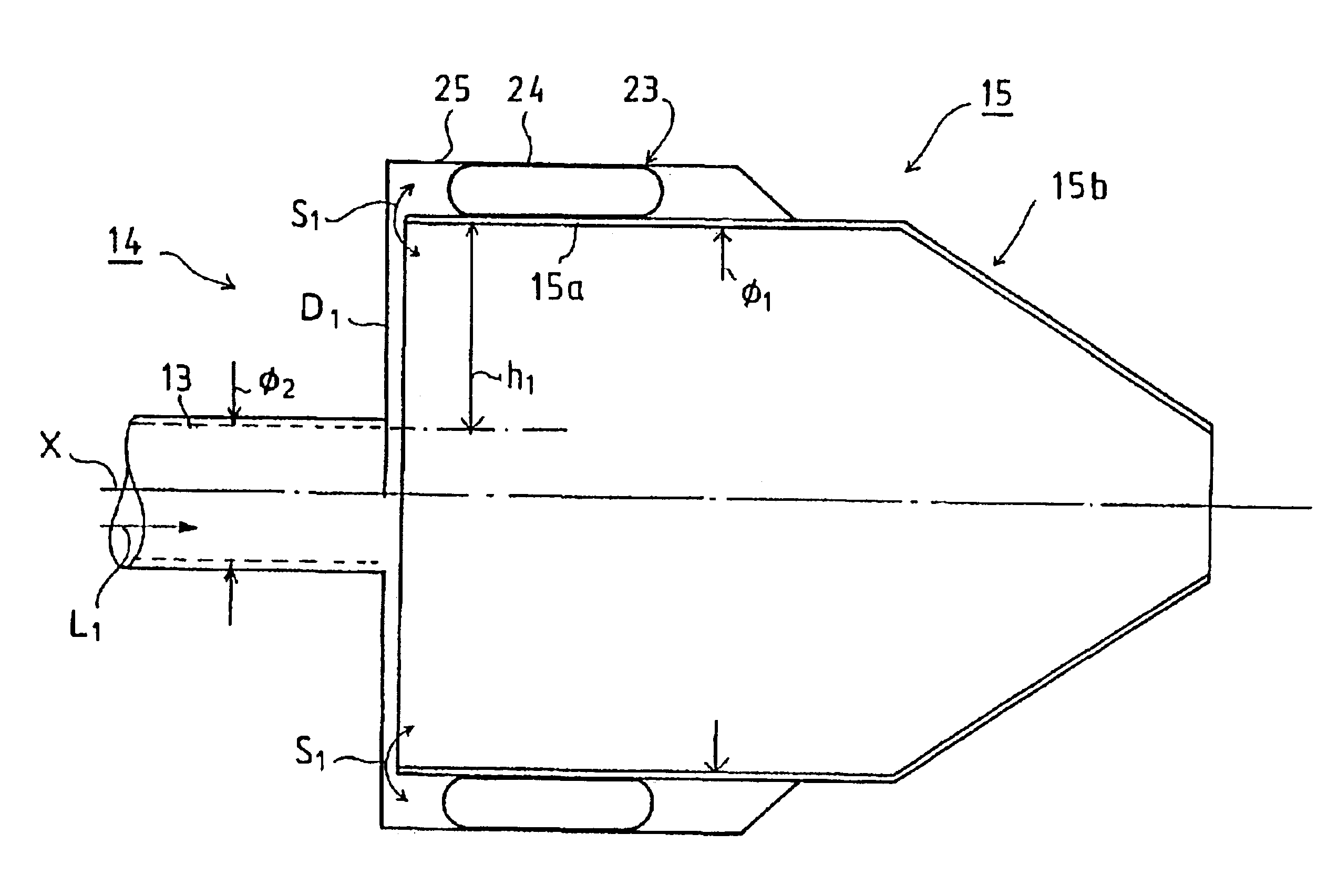
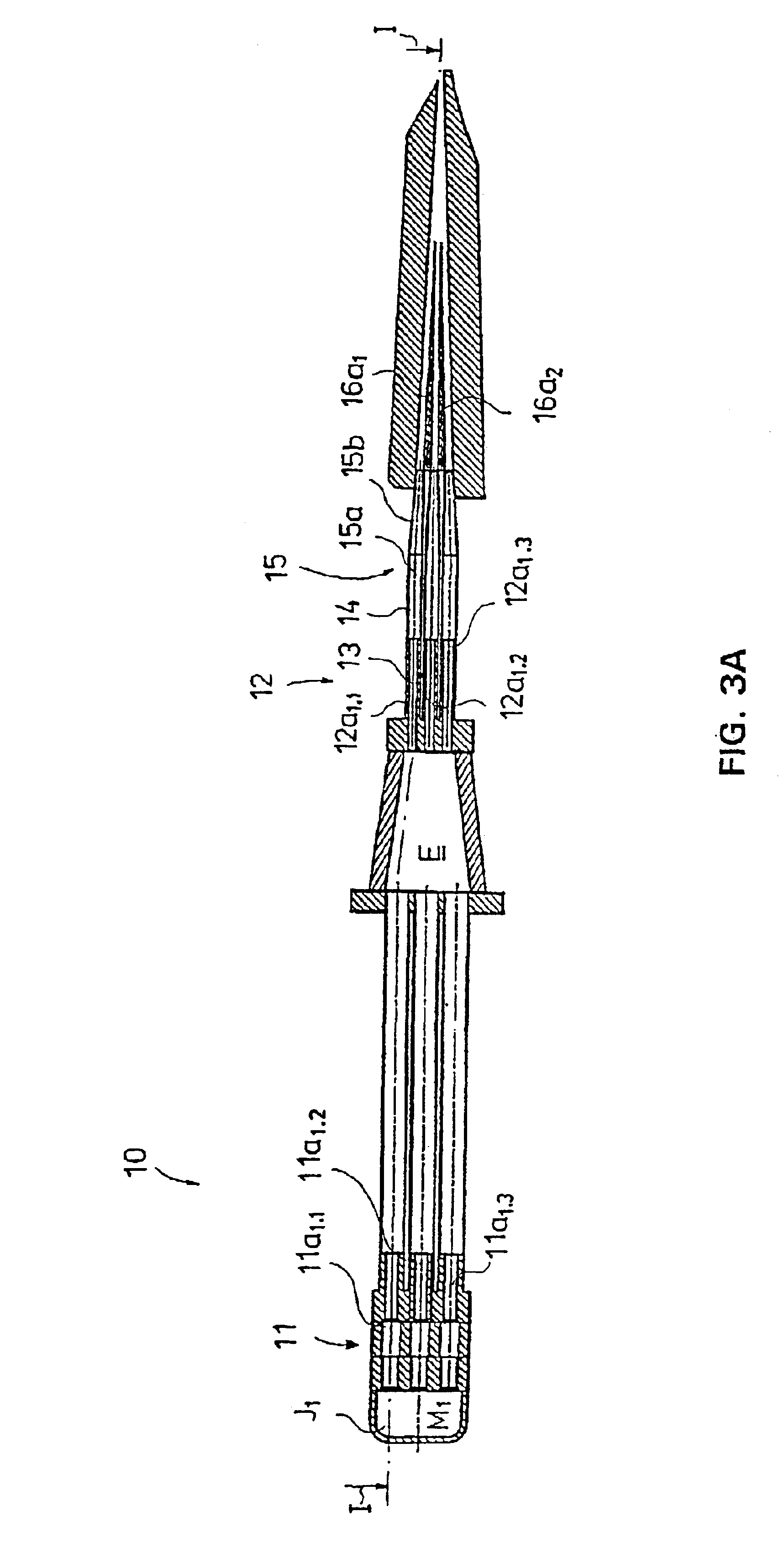
A method for fluidisation of a pulp flow in the headbox of a paper machine or such. The characteristics of the pulp flow are affected in the headbox's fluidiser (14) in one step only, whereby the height (h1) of the step is at least equal to the average fibre length, and after the fluidiser (14) the biggest permissible step expression in the flow channel in direction z is smaller than the average fibre length.

Description

BACKGROUND OF THE INVENTIONThe invention concerns a method for fluidisation of pulp flow in the headbox of a paper machine or such and control equipment used in the fluidisation.The making of paper of a good quality and a stable production process make high demands on the headbox of the paper machine. In particular, a headbox meeting qualitative and productive requirements is expected to be able to produce a homogenous and trouble-free lip discharge.Various applications in operation and further refinement processes make high qualitative demands on paper and board products. In practice, these demands concern the structural, physical and visual characteristics of the products. In order to achieve characteristics suitable for each individual purpose the production processes are optimised at each time for a certain working range, which sets limits usually also limiting the quantity of production. Thus, a product of the desired kind can be made only in a narrow working range of the produ...

Claims


Application Information

Patent Timeline
Patent Type & Authority Patents(United States)
IPC IPC(8): D21F1/02
CPCD21F1/02D21F1/028D21F1/026D21F1/024
Inventor LEPOMAKI, HANNUKAREMA, HANNUKELLOMAKI, MARKKUTUKIAINEN, MAARIT
Owner VALMET TECH INC
Learn More