
Roll, in particular, calender roll

Inactive Publication Date: 2006-03-28
WALZEN IRLE
View PDF10 Cites 4 Cited by
  • Summary
  • Abstract
  • Description
  • Claims
  • Application Information

AI Technical Summary

Benefits of technology

[0009]It is an object of the present invention to improve the quality of paper processing rolls and to also indicate a manufacturing method such that the roll, under production conditions, in the paper-making machine assumes an optimal shape quality or concentric running quality for the process.
[0011]With the paper processing roll according to the invention it is possible for the first time to employ such roll with satisfactory results as fast-running calender rolls and, accordingly, to integrate it directly into the paper-making machine. Also, the paper quality produced in the past on conventional calenders can be improved with the inventive roll and the risk of barring and the resulting markings and wear on the elastic covers are minimized. When the surface treatment of the rolls is carried out at a temperature which corresponds to the operating temperature present later during use, heat-caused deformations of the rolls during operation or during heating to the operating temperature are prevented. A thermal expansion will transform the roll into the state in which its surface had been machined or treated so that the precise geometry which had been produced during machining, in particular, during grinding of the roll, is regained.
[0014]When during the manufacture the roll surface is cooled at least over portions thereof, the heat transfer of a roll operating at increased operational temperature onto a paper web in contact therewith can be simulated, for example. In this way, a deformation of the roll, in particular, the creation of a polygon effect can be taken into consideration. Particularly, when the cooled area in its dimensions corresponds to the area which is in contact with the paper web during operation, the deformations resulting therefrom can be very precisely provoked during manufacture. The grinding and / or balancing can then be carried out under these deformation conditions which correspond precisely to the operating state. Accordingly, in the subsequent operation, as a result of the deformation which then occurs, a return into precisely the state during manufacture is achieved so that the machining dimensions of the manufacture process correspond precisely to the dimensions during operation. With this method, a constriction of the roll underneath the paper web is thus prevented as well as the formation of so-called oxbow effects and the creation of the polygon effect where the round contour shape of the roll is deformed to a polygon with the risk of barring. In particular the polygon effect, if no further measures are taken, can cause a considerable dimensional change and thus service limitation of the roll during operation.

Problems solved by technology

This means that the calender arrangement must meet the challenge of the requirements of the paper-making machines with respect to production speed, reliability etc.
In view of the considerable size of conventional calender rolls—length of more than 10 meters, weight of several tens of tons—such an operation can result in considerable loading of the bearings which support the rolls, of the elastic roll covers provided on the counter rolls, as well as of the stands.
Disruptive effects, no matter what their origin, can excite vibrations as a result of which the elastic covers will become marked and a uniform running of the rolls can no longer be ensured.
The running behavior of the thermal roll can contribute to the occurrence of the widely known, but up to the present not yet solved, barring problem because, possibly, a system-own vibration can be triggered.
Erratic running of the roll or the existence of a barring problem often leads to a prematurely required exchange of the rolls and an increased wear of the elastic roll covers, which cause a high economic loss for the operator of such a device.
In off-line calenders this is counteracted in that the production speed is lowered, which however does not solve the problems but simply weakens the effects (marking of the roll covers and of the product).
In the case of calenders that are installed online this is not an option.
The roll shape is to be viewed as particularly critical because the calender rolls impart to the paper its optical and haptic properties and deformations of the calender rolls, even in the micrometer range, result in clearly visible imperfections of the paper quality and the properties of the elastic roll covers.
The quality requirements for high-quality paper can possibly no longer be fulfilled when the roll shape is not sufficiently precise.

Method used


Image

  • Roll, in particular, calender roll
  • Roll, in particular, calender roll

Examples


Embodiment Construction

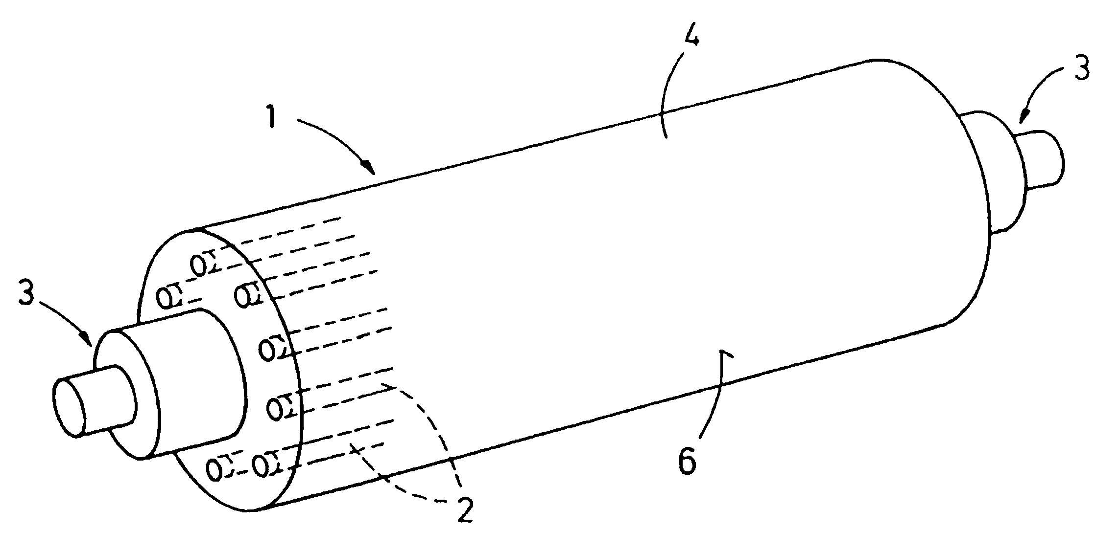
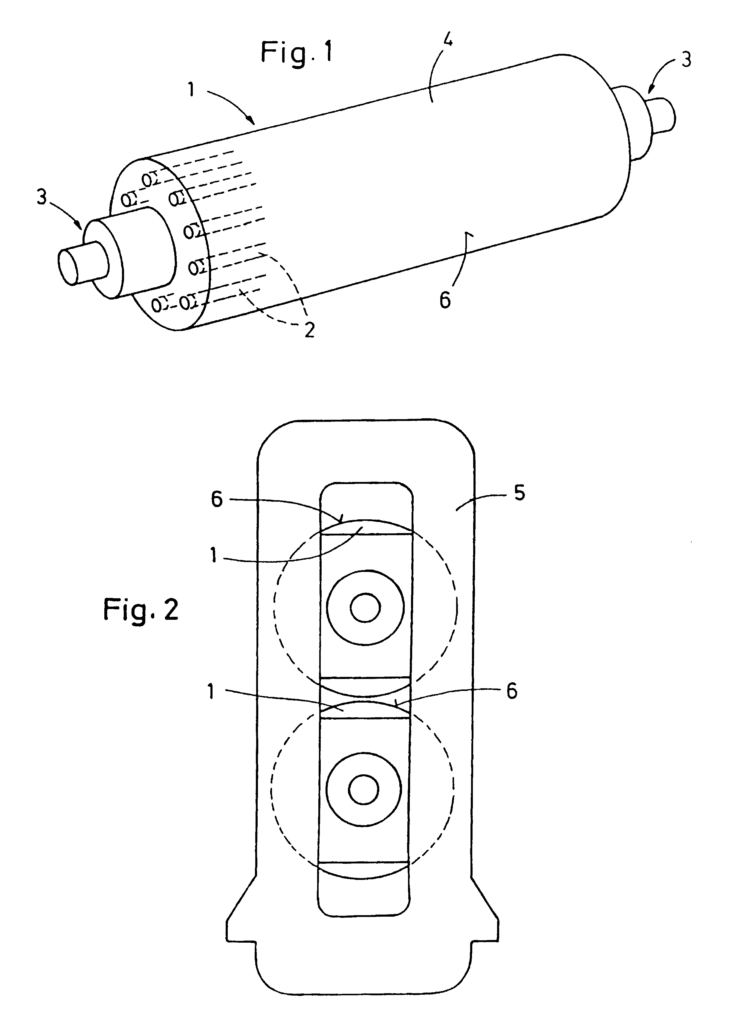
[0018]In the illustrated embodiment, a heatable roll 1 with inner bores 2 is illustrated. The bores 2 extend axially and are provided for guiding a heating medium through during operation (paper making) and during manufacture of the roll 1. The heating medium can be a pre-heated fluid such a heat carrier oil, water or steam. The bores 2 can be provided, for example, in the mantle of the hollow-cylindrical roll 1.

[0019]For clamping the roll 1, symmetrically formed flange journals 3 are provided which limit the roll body 4 at both ends and which point outwardly in order to be received in bearing eyes of a stand 5.

[0020]Typical paper processing rolls 1, which are used as calender rolls for calendering a paper web, are comprised, for example, of chilled iron, centrifugal casting or also, up to a certain degree, of forged steel. Such materials are inhomogeneous (anisotropic and orthotropic) which, with respect to the shaping precision is particularly problematic. The dimensions of the ro...


PUM

PropertyMeasurementUnit
Temperatureaaaaaaaaaa

Abstract

A paper processing roll for use in a calender of a paper-making machine which during operation can be exposed to increased temperatures is provided with a heat-treated surface which is produced by hot-grinding or hot-balancing or both.

Description

BACKGROUND OF THE INVENTION[0001]1. Field of the Invention[0002]The invention relates to a paper processing roll, in particular, for use within a paper calender, wherein the roll during operation can be exposed to increased temperature, as well as to a method for producing a roll usable in paper processing, in particular, for use in the calender of a paper-making machine.[0003]2. Description of the Related Art[0004]In paper processing, for example, for glossing or other treatments of the paper surface, a paper web is guided through a roll gap (nip) of a calender arrangement. This is the case in calenders or a glazing apparatus installed online or off-line, independent of their configuration. The continuously increasing production velocities and the multi-nip calenders which are currently on the market pose new requirements in regard to the quality of thermal rolls. Moreover, high-quality paper products which, in the past, have been processed without exception with off-line super cal...

Claims


Application Information

Patent Timeline
IPC IPC(8): D21G1/02B24B5/37F16C13/00
CPCD21G1/0246D21G1/0266Y10T29/4956
Inventor VON SCHWEINICHEN, JAXASCHRAMM, KLAUS-PETERWIERTZ, WOLFGANGHELLENTHAL, LUDWIG
Owner WALZEN IRLE
Learn More