Recoil starter

a technology of recoil starter and recoil spring, which is applied in the direction of engine starter, machine/engine, muscle operated starter, etc., can solve the problems of large damper spring distortion amount, difficult to start the engine, and deterioration of the functions of the recoil starter at the time the engine is started, so as to prevent a deterioration in the function improve the durability of the recoil starter

Inactive Publication Date: 2005-12-06
STARTING IND CO LTD
View PDF8 Cites 28 Cited by
  • Summary
  • Abstract
  • Description
  • Claims
  • Application Information

AI Technical Summary

Benefits of technology

[0010]The present invention has been made so as to solve the problems of the above-described conventional technology. Accordingly, it is an object of the present invention to provide a recoil starter capable of suppressing vibration of a damper spring resulting from vibrations during running of an engine, to thereby prevent a deterioration in functions of the recoil starter at the time an engine is started resulting from abrasion of a part thereof, such as a rope reel or a cam, made of a plastic material, resulting in the durability of the recoil starter being improved.
[0011]It is another object of the invention to provide a recoil starter that prevents a constriction phenomenon of a damper spring and prevents a reduction in durability resulting from repeated excessive deformations of the damper spring.
[0012]It is still another object of the invention to provide a recoil starter that can effectively transmit a pulling force exerted on an operating handle to an engine without fluctuations of a load of the engine being directly transmitted to the operating handle adapted to pull a recoil rope.

Problems solved by technology

Usually, parts such as the rope reel, the clutch body and the like are formed of plastic materials in order to reduce costs and weight, and sometimes the opening portion of the clutch body and the engagement portion of the rope reel which are constantly in contact with the damper spring are abraded, which causes a play in a rotational direction between the damper spring and the rope reel or the clutch body, whereby the problem arises that functions of the recoil starter at the time the engine is started are deteriorated.
When the damper spring constricts the outer peripheral surface of the clutch body or the rope reel, the damper spring becomes unable to absorb fluctuations of the load, and a great shock due to the fluctuations of the load of the engine is transmitted to the operating handle pulling the recoil rope, which makes it difficult to start the engine.
Although it is conceivable to avoid the constriction phenomenon by setting the outer diameters of the rope reel and clutch body and the diameter of the damper spring in the conventional technology with a sufficient difference in view of constriction, when the load of the engine is large, the distortion amount of the damper spring becomes large and the damper spring is greatly distorted or deformed each time the engine is started.
Due to the damper spring being repeatedly deformed such a large distortion amount, the life span of the damper spring becomes short, resulting in the durability of the recoil starter being reduced.

Method used


Image

  • Recoil starter
  • Recoil starter
  • Recoil starter

Examples


Embodiment Construction

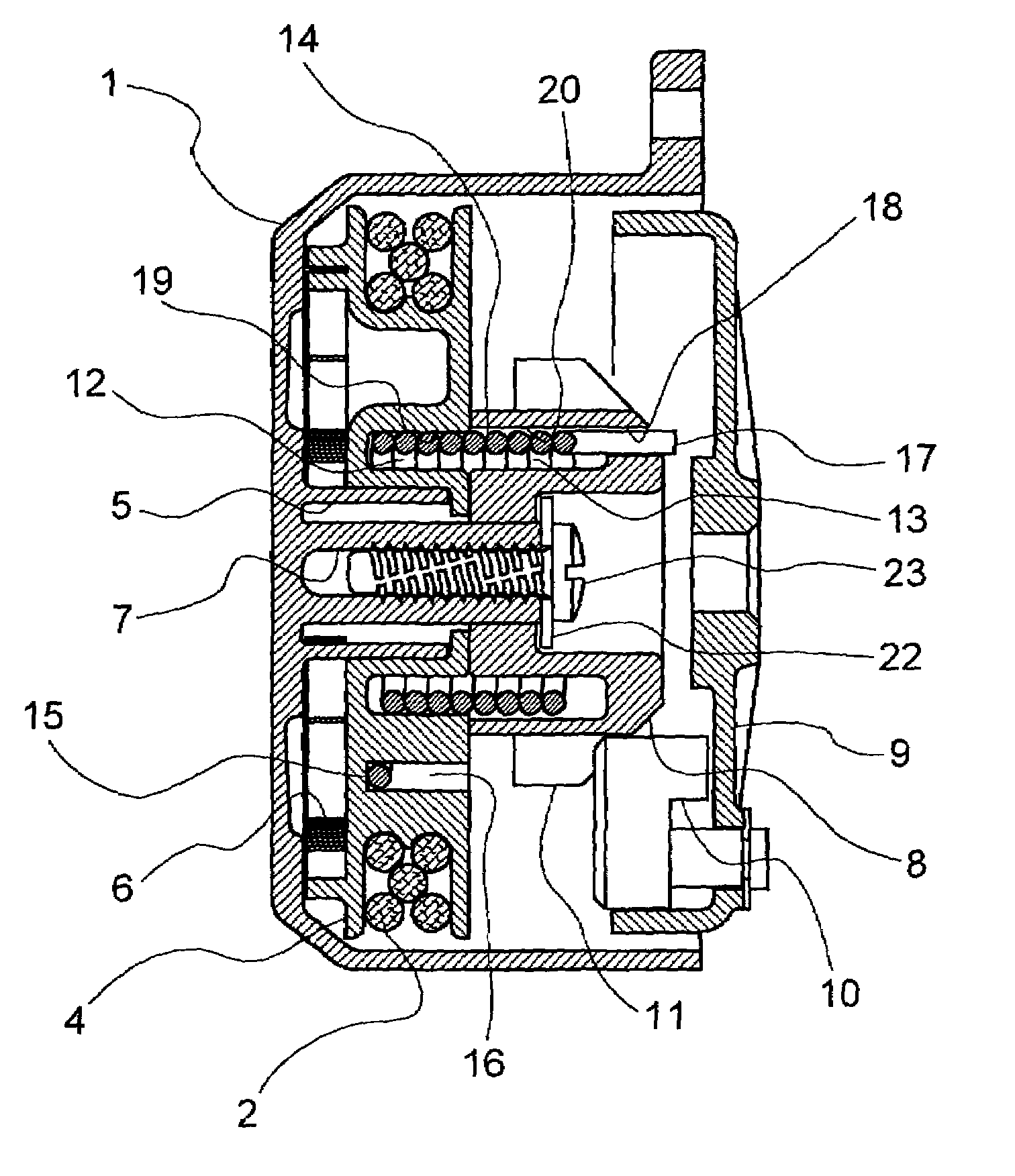
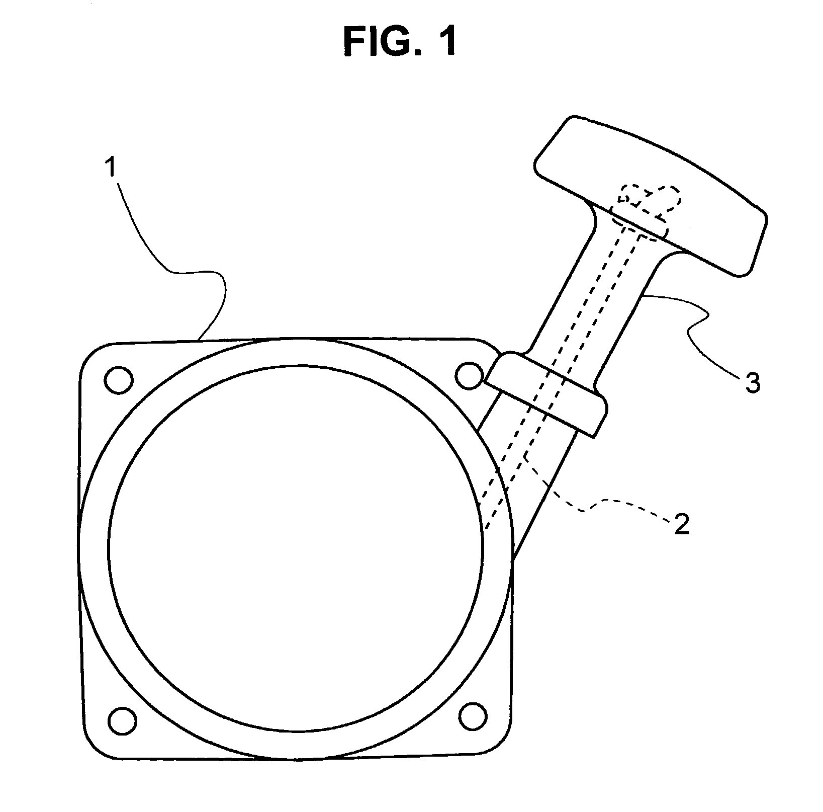
[0039]Embodiments of the invention will now be described with reference to the accompanying drawings. FIGS. 1 to 5 show a recoil starter according to a first embodiment of the invention. As shown in FIG. 1, the recoil starter is so constructed that by pulling an operating handle 3 attached to an end of a recoil rope 2 that is drawn out to the outside of a starter housing 1, a drive section mounted within the starter housing 1 is rotatingly driven, a crankshaft of an engine is rotated by the rotation of the drive section, whereby the engine is started.

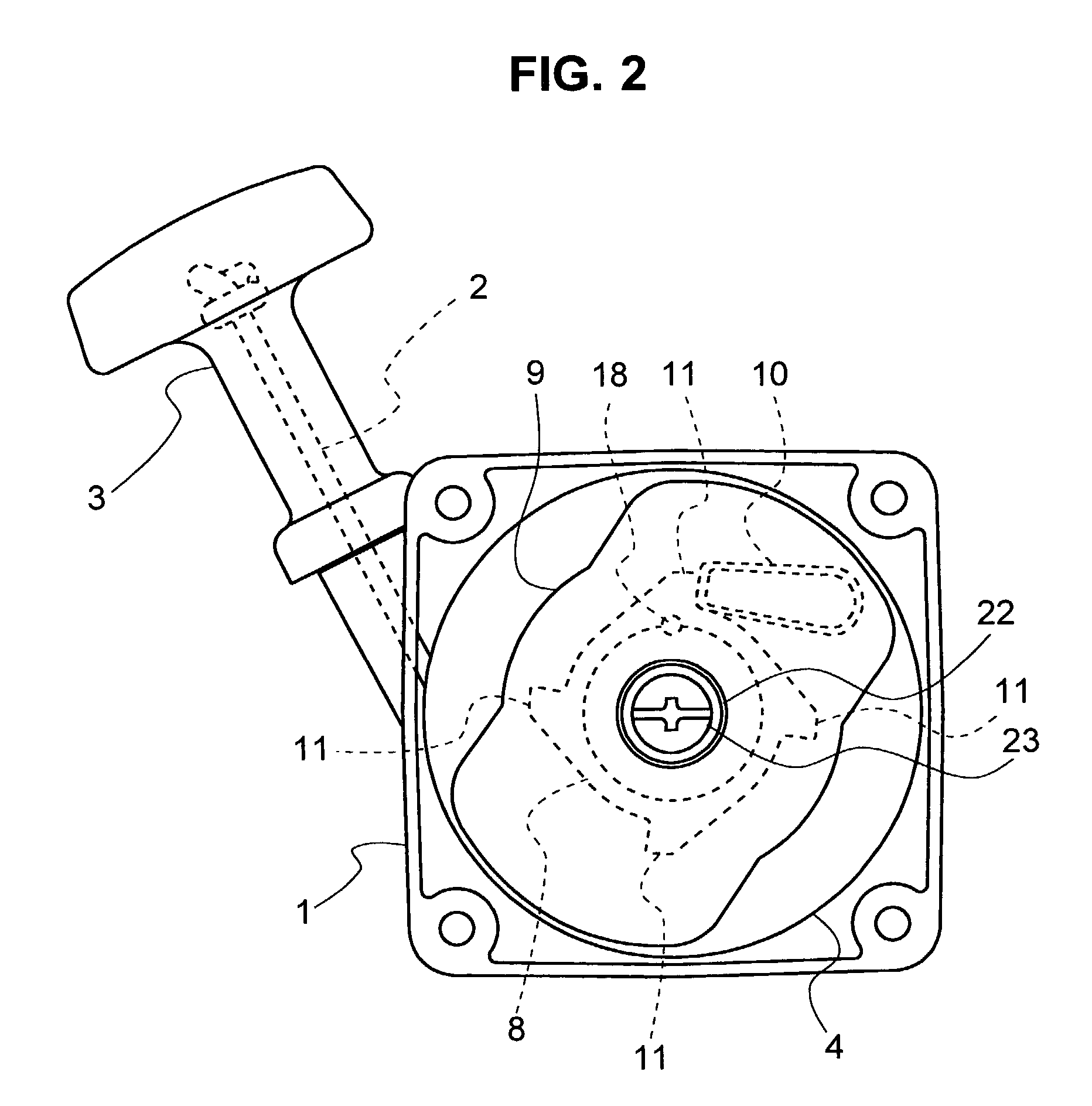
[0040]As shown in FIGS. 2 and 3, the drive section is constituted by a rope reel 4 having the recoil rope 2 wound thereon, one end of which is pulled out to the outside of the starter housing 1, and a cam 8 that transmits a rotational force of the rope reel 4 in an engine starting direction to the engine via a one-way rotative mechanism. The rope reel 4 is rotatably supported by a reel support shaft 5 integrally formed on an inner side ...


PUM


Abstract

A recoil starter capable of preventing vibration of a damper spring due to vibrations of an engine caused during running of the engine, to thereby restrain abrasion of a rope reel, a cam and the like which are made of a plastic material, resulting in the durability of the recoil starter being enhanced. The recoil starter includes a drive section comprised of a rope reel which is rotated by pulling a recoil rope and a cam for transmitting the rotational force of the reel to a crankshaft of the engine through a one-way rotative transmission mechanism. A damper spring in the shape of a torsion coil spring is held in annular recesses formed in joint surfaces of the rope reel and cam to face each other while the damper spring is resiliently distorted, so that the rope reel and the cam are rotatingly coupled with each other through the damper spring.

Description

BACKGROUND OF THE INVENTION[0001]1. Field of the Invention[0002]The present invention relates to a recoil starter having a recoil rope wound around a rope reel rotatably supported inside a starter housing, wherein the recoil rope is pulled via an operating handle joined to an end of the recoil rope to rotate the rope reel so that the rotational force of the rope reel is transmitted via a one-way rotative mechanism, such as a clutch mechanism or a centrifugal ratchet, to a drive pulley fixed at a crankshaft of an engine, whereby the crankshaft of the engine is rotated due to the rotation of the drive pulley, resulting in the engine being started.[0003]2. Description of the Related Art[0004]A recoil starter, wherein an operating handle disposed on the outside of a starter housing is pulled, a rope reel having a recoil rope wound therearound, an end of which is connected to the operating handle, is rotated, the rotational force of the rope reel is transmitted via a one-way rotative mec...

Claims


Application Information

Patent Timeline
Patent Type & Authority Patents(United States)
IPC IPC(8): F02N3/02F16F15/121
CPCF16F15/1216F02N3/02F02N5/02
Inventor TOHYAMA, ISAO
Owner STARTING IND CO LTD
Why Eureka
Try Eureka