
Photovoltaic roofing structure

Inactive Publication Date: 2005-04-05
UNITED SOLAR SYST
View PDF18 Cites 106 Cited by
  • Summary
  • Abstract
  • Description
  • Claims
  • Application Information

AI Technical Summary

Benefits of technology

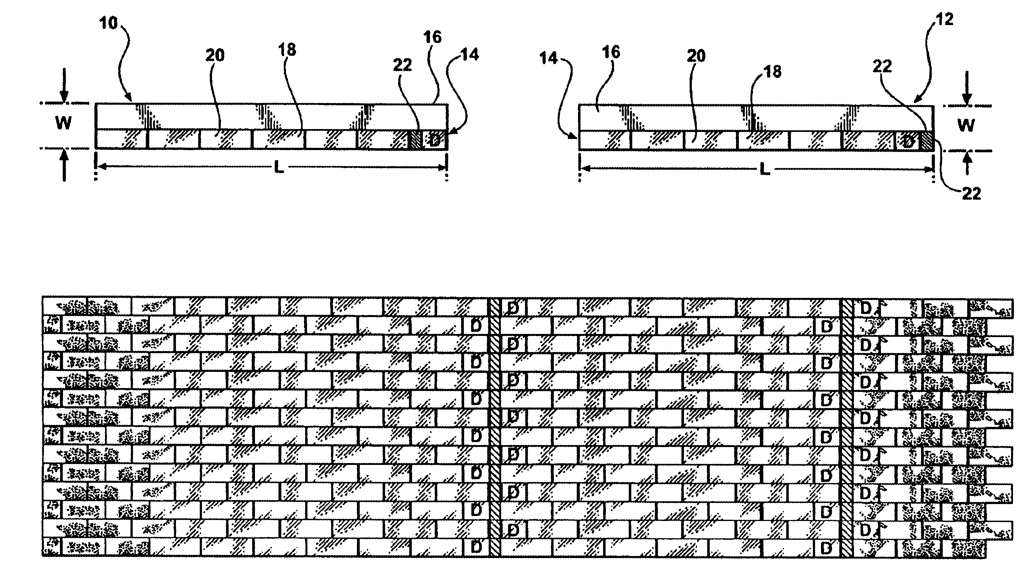
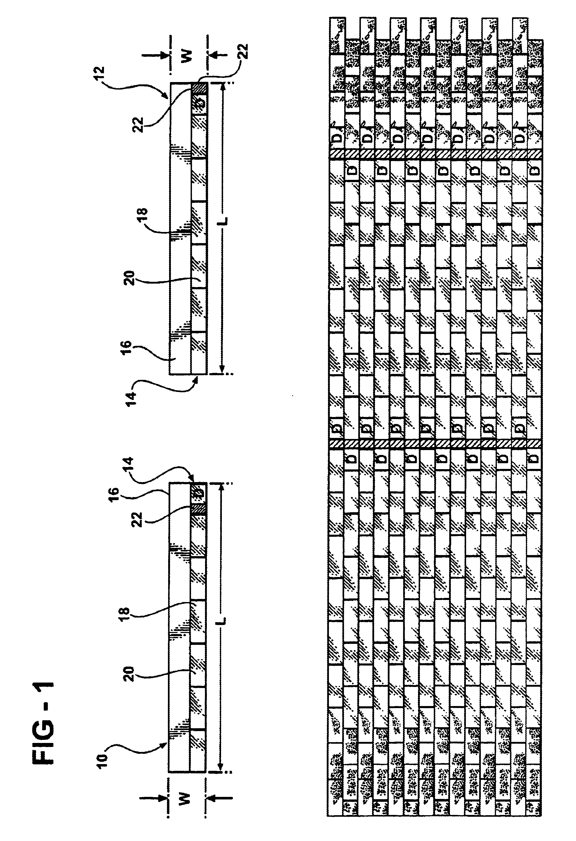
There is disclosed herein a photovoltaic shingle system. The system comprises a plurality of pairs of shingle strips. Each pair includes a first and a second member, and each of said first and second members comprises an elongated strip having a length dimension L greater than a width dimension W. Each member further comprises a photovoltaic generating portion which extends along the length dimension L. The photovoltaic generating portion has a width which is less than the width dimension W. The photovoltaic generating portion includes a plurality of tabs defined thereupon. Each tab has a width which is equal to the width of the photovoltaic generating portion and a length which is less than the length dimension L. Each photovoltaic generating portion further includes at least one photovoltaic device which is operative to generate a flow of electrical current in response to the absorption of illumination thereby. Each photovoltaic generating portion further includes an interconnect region having a width which is equal to the width of the photovoltaic generating portion and a length which is less than the length of any one of the tabs. Each photovoltaic generating portion further includes a pair of electrical terminals which are disposed in the interconnect region and which are in electrical communication with at least one photovoltaic device. The terminals are operative to provide for the collection of the flow of electrical current generated by said at least one photovoltaic device. Each member further includes an overlap portion having a length equal to the length dimension L and a width which is less than the width dimension

Problems solved by technology

Many of such prior art structures are cumbersome, expensive, and very difficult to install.
Such “backside” connections can be difficult to implement, particularly when the shingles are installed onto buildings which do not have full attics or other access to the underside of the roof.
In some instances, the through hole connections in the roof are perceived as compromising the integrity of the roof.
Also, the backside connection nature of such devices makes them difficult to service or replace.

Method used


Image

  • Photovoltaic roofing structure
  • Photovoltaic roofing structure
  • Photovoltaic roofing structure

Examples


Embodiment Construction

The photovoltaic roofing system of the present invention is based upon photovoltaic shingle material which is generally similar to the material described in the '735 and '861 patents; although, it is to be understood that shingles manufactured from photovoltaic materials other than those disclosed herein, as well as roofing materials of other configurations and designs, may likewise be employed in the present invention.

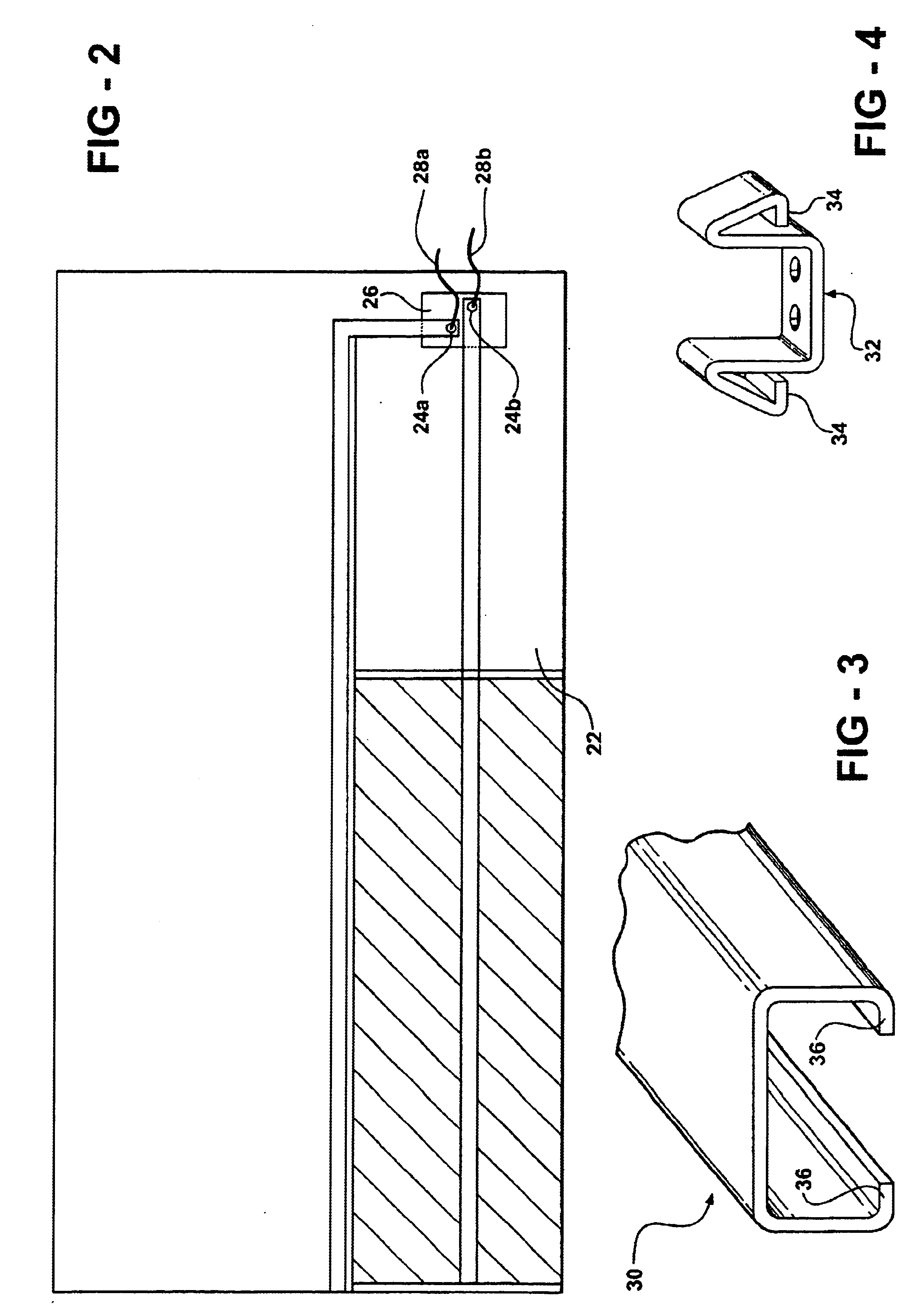
According to the present invention, the photovoltaic roofing system is based upon the use of a plurality of pairs of photovoltaic shingle material. The materials are configured to allow for front surface connection, and the system further includes an electrical interconnect system and a cap member for protecting the integrity of the connections.

Referring now to FIG. 1, there is shown one embodiment of the present invention. As will be seen, the roofing system is based upon the use of a plurality of pairs of photovoltaic shingle material, and FIG. 1 shows a first membe...


PUM


Abstract

A photovoltaic roofing system includes front surface electrical connections and can be installed utilizing conventional tools and techniques. The system includes particularly configured photovoltaic power generating roofing shingles which provide for linearly aligned electrical terminals when installed. The system may be used in conjunction with a protective cap which shields the connections.

Description

FIELD OF THE INVENTIONThis invention relates to photovoltaic devices, and more particularly to a roofing material which is capable of generating electrical power. Most specifically, the invention relates to an electrical power generating roofing shingle which is compatible with conventional shingles, and which embodies front surface electrical connections.BACKGROUND OF THE INVENTIONPhotovoltaic energy is becoming a very significant source of electrical power. The roofs of building structures are directly exposed to solar radiation, and are particularly well suited for supporting photovoltaic generating devices. In this regard, the prior art has developed various roofing structures and members which are capable of generating photovoltaic power. Many of such prior art structures are cumbersome, expensive, and very difficult to install. Therefore, the prior art has sought methods and devices whereby a photovoltaic generating material may be disposed upon a roofing structure by simple t...

Claims


Application Information

Patent Timeline
IPC IPC(8): H01L25/00H01L31/048H01L31/05
CPCH01L31/02008H02S40/34H02S20/23Y02B10/12Y10S136/291Y02E10/50Y02B10/10
Inventor GUHA, SUBHENDUELLISON, TIM
Owner UNITED SOLAR SYST
Learn More