
Farady rotation device and optical device comprising it

a technology of rotation device and optical device, which is applied in the direction of instruments, non-linear optics, optics, etc., can solve the problems of wavelength-dependent loss (attenuation amount change with a change of wavelength) that has not yet been solved, and achieves the effect of reducing wavelength-dependent loss

Inactive Publication Date: 2005-04-05
KOHOKU KOGYO CO LTD
View PDF17 Cites 7 Cited by
  • Summary
  • Abstract
  • Description
  • Claims
  • Application Information

AI Technical Summary

Benefits of technology

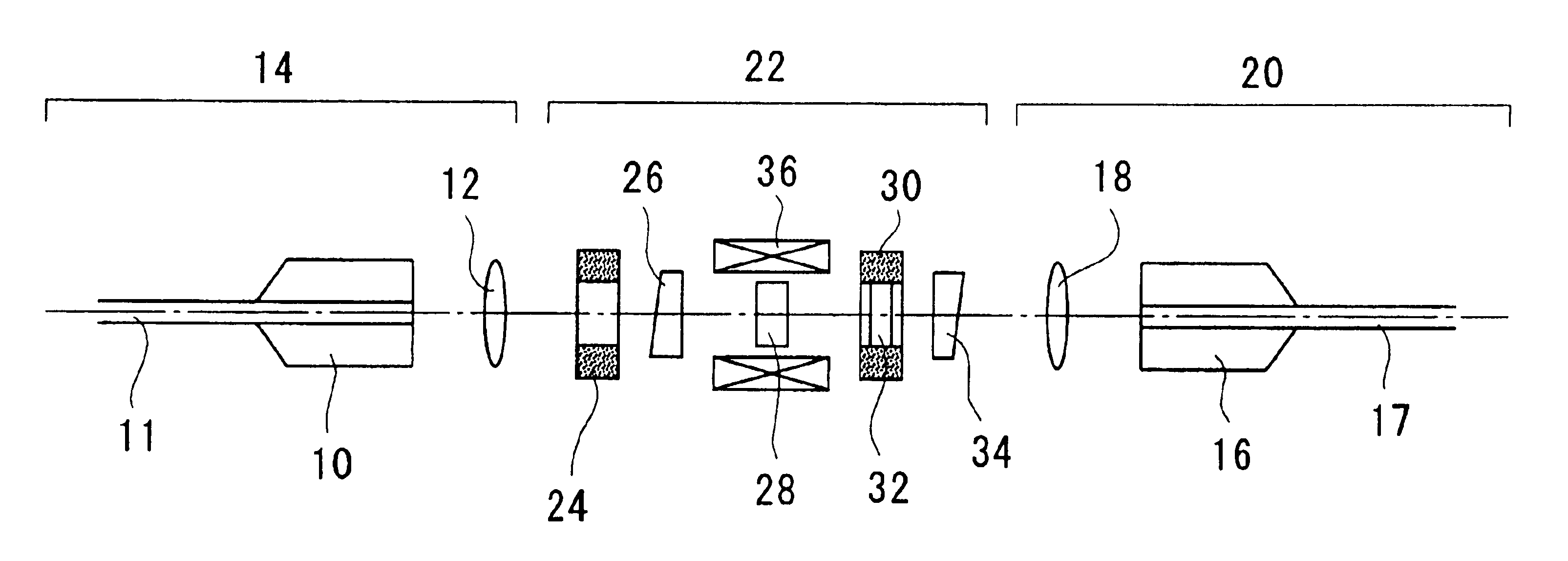
From the above, it is a principal object of the present invention to provide a Faraday rotation device which is improved in wavelength and temperature characteristics by making a structure to be reverse acted with the wavelength and temperature coefficients of Faraday rotation angle while using a plurality of Faraday elements having the same rotation direction.
Another object of the present invention is to provide various optical devices, such as an optical attenuator, which are reduced in wavelength dependence and temperature-dependent loss by making a structure to be reverse acted with the wavelength and temperature coefficients of Faraday rotation angle while using a plurality of Faraday elements having the same rotation direction.
Further object of the present invention is to provide a variable optical attenuator which is reduced in wavelength-dependent loss.
Yet another object of the present invention is to provide a variable optical attenuator having a structure not requiring to distinguish between input and output.
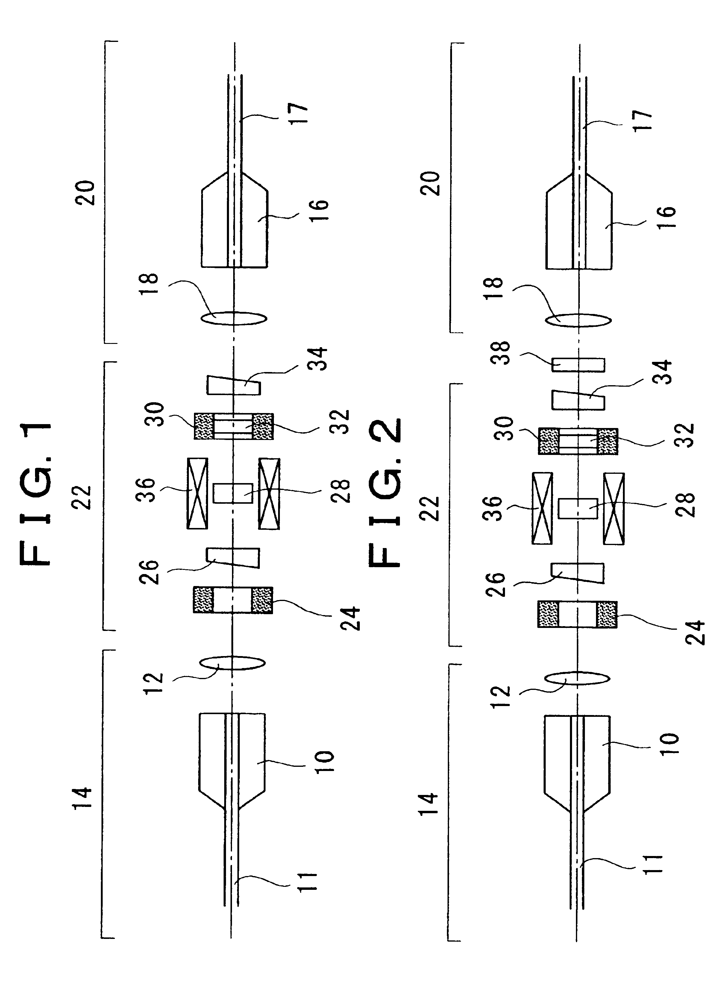
In this manner, the wavelength dependence, as an optical attenuator, can be reduced by adding an optical filter functioning part reverse in characteristic to a wavelength-dependent loss as optical attenuator to be caused due to a wavelength characteristic of Faraday rotation angle possessed by the Faraday element.
By thus setting the optical filter functioning part with a wavelength-dependent loss, it is possible to more effectively reduce the wavelength-dependent loss as a variable optical attenuator.

Problems solved by technology

However, the use of a composite polarization prism reduces the amount of incident light by the polarizer by half.
However, the problem of wavelength-dependent loss (attenuation amount change with a change of wavelength) has not yet been solved.
At this time, the synthesized signal light causes a wavelength-dependent loss due to the optical attenuator, which worsens the gain flatness characteristic of the wavelength division multiplex system.
For this reason, it is of an extreme important technical problem to suppress, to the minimum, the wavelength-dependent loss at the time of light attenuation.
However, it is not necessarily easy to make a suitable compensation film corresponding to an arbitrary basic film.
This is because, although the wavelength characteristic and temperature characteristic of the basic film and compensation film must be offset to a possible great extent, there is limitation in material design due to quite different compositions between the two.

Method used


Image

  • Farady rotation device and optical device comprising it
  • Farady rotation device and optical device comprising it
  • Farady rotation device and optical device comprising it

Examples


example 1

For a Case of θ1max=−θ2

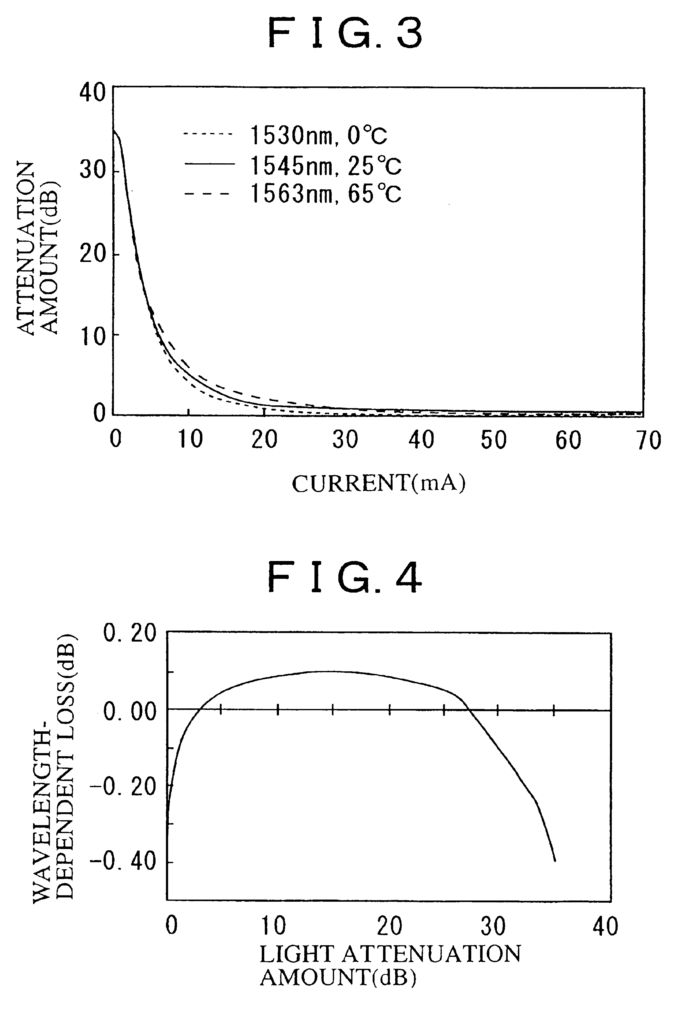
For example, in case the rotation angle on the first Faraday element 28 at an electromagnet variable magnetic field of zero is 96 degrees, the rotation angle on the second Faraday element is −96 degrees, the angle which is defined by the optical axes of the polarizer and analyzer is 90 degrees, and the optical filter characteristic is given as X≈−(WDL1+WDL2) / 2 or X≈−(WDL3+WDL4) / 2 as described above, then the sign is opposite between the Faraday rotation angle wavelength coefficient and temperature coefficient of the first Faraday element and second Faraday element. Consequently, it is possible to realize a variable optical attenuator having an extremely reduced temperature•Faraday rotation angle wavelength-dependence characteristic in the high attenuation range, at an electromagnet magnetic field of zero (current: 0 mA) Furthermore, the wavelength-dependent loss can be reduced in an arbitrary service attenuation range by the optical filter characteristic. FIG...

example 2

For a Case of −θ2=θ1

Because the wavelength coefficients of both of the first and second Faraday elements are opposite in sign, the Faraday rotation angle wavelength dependence is offset, thus obtaining a point where the wavelength dependence is zero. This point of zero can be determined at an arbitrary light attenuation amount by arranging θ2 within a range |θ1min|≦|θ2|≦|θ1max| and adjusting the angle which is defined by the optical axes of the polarizer and analyzer. For example, in the case where the rotation angle on the first Faraday element at an electromagnet magnetic field of zero is 96 degrees, the rotation angle on the second Faraday element is −15 degrees, and the angle which is defined by the optical axes of the polarizer and analyzer is 90 degrees, then a crossed-Nicols state is reached at a rotation angle of first Faraday element of 15 degrees wherein the attenuation amount is at the maximum. The wavelength dependence is offset by the second Faraday element (see FIG. 1...


PUM

PropertyMeasurementUnit
angleaaaaaaaaaa
Faraday rotation angleaaaaaaaaaa

Abstract

Optical devices including a Faraday rotation devices improved in wavelength and temperature characteristics and an optical attenuator reduced in wavelength dependence and temperature-dependent loss. The Faraday rotation device has permanent magnets magnetized in an axial direction of through-holes, and Faraday elements having a same Faraday rotation direction with respect to a same magnetization direction. The permanent magnets are directed in the same magnetization direction along an optical path, where part of the Faraday elements are accommodated in the through-hole of the permanent magnet, and the remaining Faraday elements are arranged between the magnets, whereby the Faraday elements are to be applied by magnetic fields in opposite directions. For a device variable in Faraday rotation angle, an electromagnet is provided. An input fiber collimator and polarizer are provided on an input side of with the Faraday elements while an analyzer and output fiber collimator are on an output side.

Description

TECHNICAL FIELDThe present invention relates to a Faraday rotation device having Faraday elements that are provided at the inside and outside of an annular permanent magnet so that magnetic fields can be applied in opposite directions to the Faraday elements, and to an optical device using the same. More specifically, the present invention relates to a Faraday rotation device including a plurality of permanent magnets which have through-holes that are arranged so as to be directed to the same magnetization direction along an optical path so that part of a plurality of Faraday elements, in the same Faraday rotation direction with respect to the same magnetic field direction, is accommodated in the through-hole of the permanent magnet while the remaining ones are arranged between the permanent magnets, thereby enabling magnetic fields to be applied in opposite directions to the part of the Faraday elements and the remaining Faraday elements. This device is useful for an optical attenu...

Claims


Application Information

Patent Timeline
Patent Type & Authority Patents(United States)
IPC IPC(8): G02F1/09G02F1/01
CPCG02F1/09G02F1/093G02F2203/48G02F2203/04G02F2201/16
Inventor SAHASHI, TERUHISANAKADA, HIDENORIKAWAI, HIROTAKAKOJIMA, ISAOTOKUMASU, TSUGIO
Owner KOHOKU KOGYO CO LTD
Learn More