

Faraday rotation device and optical device using same
a technology of rotation device and optical device, which is applied in the field of rotation device, can solve the problems of wavelength-dependent loss (attenuation amount change with a change of wavelength) that has not yet been solved, and achieve the effect of improving wavelength and temperature characteristics
- Summary
- Abstract
- Description
- Claims
- Application Information
AI Technical Summary
Benefits of technology
Problems solved by technology
Method used
Image

Examples
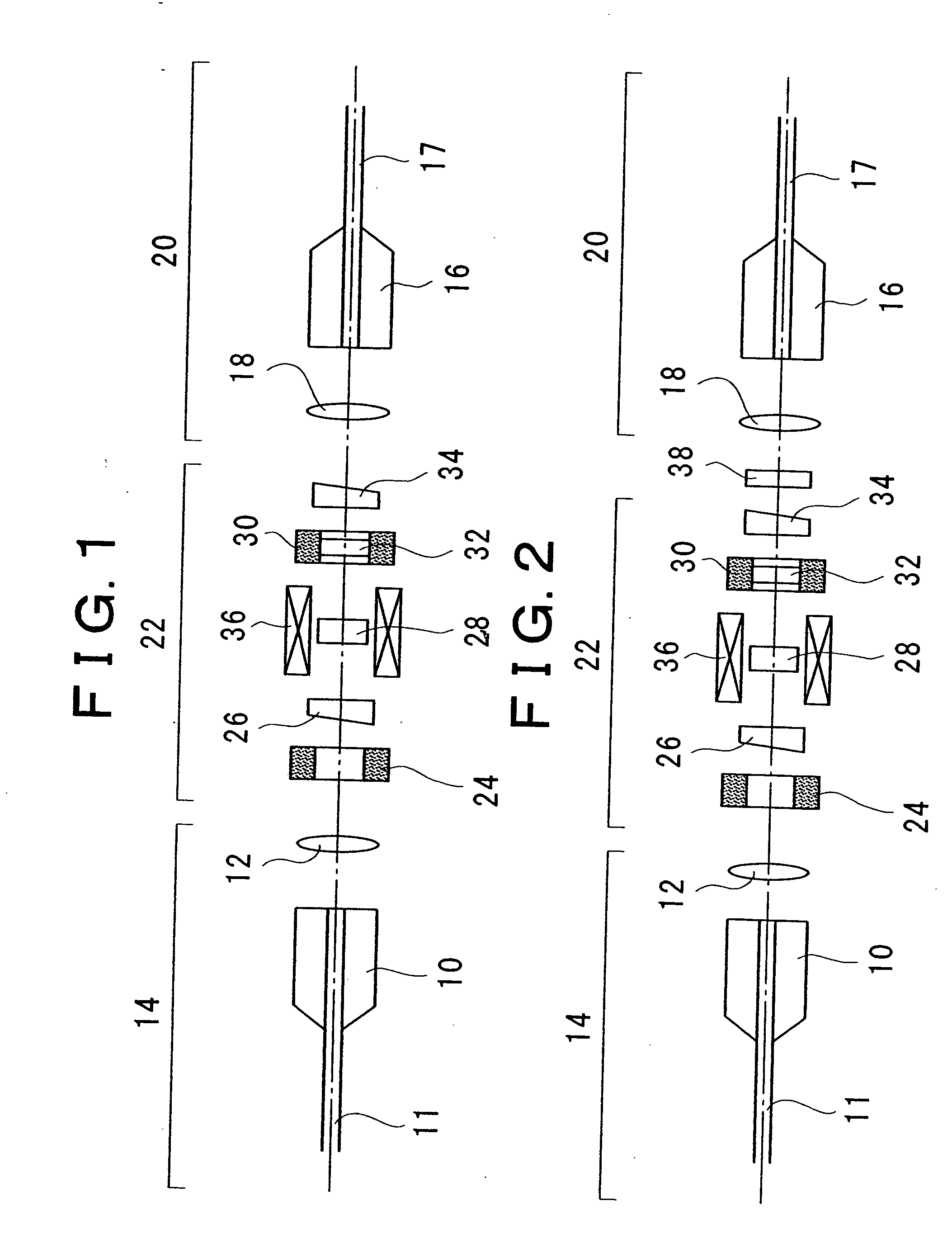
example 1
For a case of θ1max=−θ2
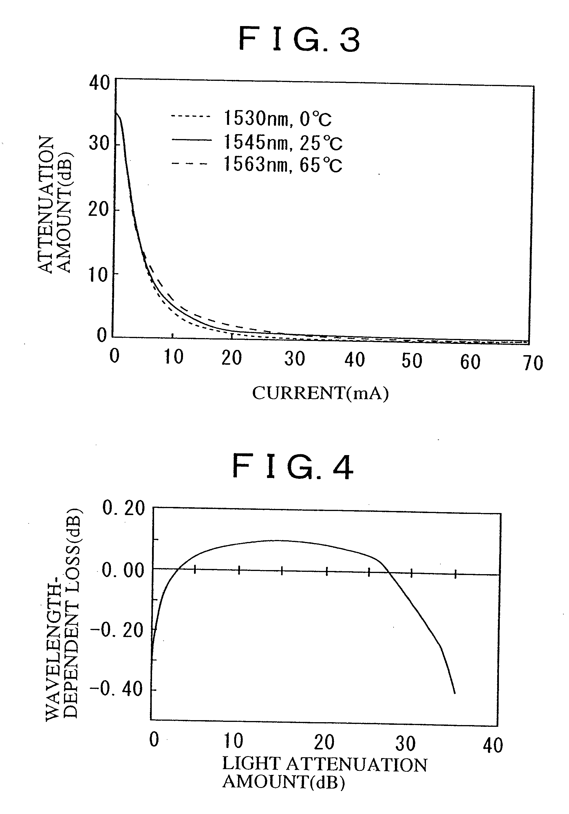
[0107] For example, in case the rotation angle on the first Faraday element 28 at an electromagnet variable magnetic field of zero is 96 degrees, the rotation angle on the second Faraday element is −96 degrees, the angle which is defined by the optical axes of the polarizer and analyzer is 90 degrees, and the optical filter characteristic is given as X≈−(WDL1+WDL2) / 2 or X≈−(WDL3+WDL4) / 2 as described above, then the sign is opposite between the Faraday rotation angle wavelength coefficient and temperature coefficient of the first Faraday element and second Faraday element. Consequently, it is possible to realize a variable optical attenuator having an extremely reduced temperature•Faraday rotation angle wavelength-dependence characteristic in the high attenuation range, at an electromagnet magnetic field of zero (current: 0 mA). Furthermore, the wavelength-dependent loss can be reduced in an arbitrary service attenuation range by the optical filter characteris...
example 2
For a Case of −θ2=θ1
[0108] Because the wavelength coefficients of both of the first and second Faraday elements are opposite in sign, the Faraday rotation angle wavelength dependence is offset, thus obtaining a point where the wavelength dependence is zero. This point of zero can be determined at an arbitrary light attenuation amount by arranging θ2 within a range |θ1min|≦|θ2|≦|θ1max| and adjusting the angle which is defined by the optical axes of the polarizer and analyzer. For example, in the case where the rotation angle on the first Faraday element at an electromagnet magnetic field of zero is 96 degrees, the rotation angle on the second Faraday element is −15 degrees, and the angle which is defined by the optical axes of the polarizer and analyzer is 90 degrees, then a crossed-Nicols state is reached at a rotation angle of first Faraday element of 15 degrees wherein the attenuation amount is at the maximum. The wavelength dependence is offset by the second Faraday element (see...
PUM
| Property | Measurement | Unit |
|---|---|---|
| angle | aaaaa | aaaaa |
| Faraday rotation angle | aaaaa | aaaaa |
| Faraday rotation angle | aaaaa | aaaaa |
Abstract
Description
Claims
Application Information