Chain saw adjuster mechanism with locking teeth

a technology of adjuster mechanism and chain saw, which is applied in the direction of band saw, metal sawing accessories, manufacturing tools, etc., can solve the problems of chain saw cutting chain loose on guide bars, stretch of chain,

Inactive Publication Date: 2005-04-12
HUSQVARNA OUTDOOR PROD INC
View PDF28 Cites 43 Cited by
  • Summary
  • Abstract
  • Description
  • Claims
  • Application Information

AI Technical Summary

Problems solved by technology

A cutting chain of a chain saw may become loose on a guide bar after some amount of us

Method used


Image

  • Chain saw adjuster mechanism with locking teeth
  • Chain saw adjuster mechanism with locking teeth
  • Chain saw adjuster mechanism with locking teeth

Examples


Embodiment Construction

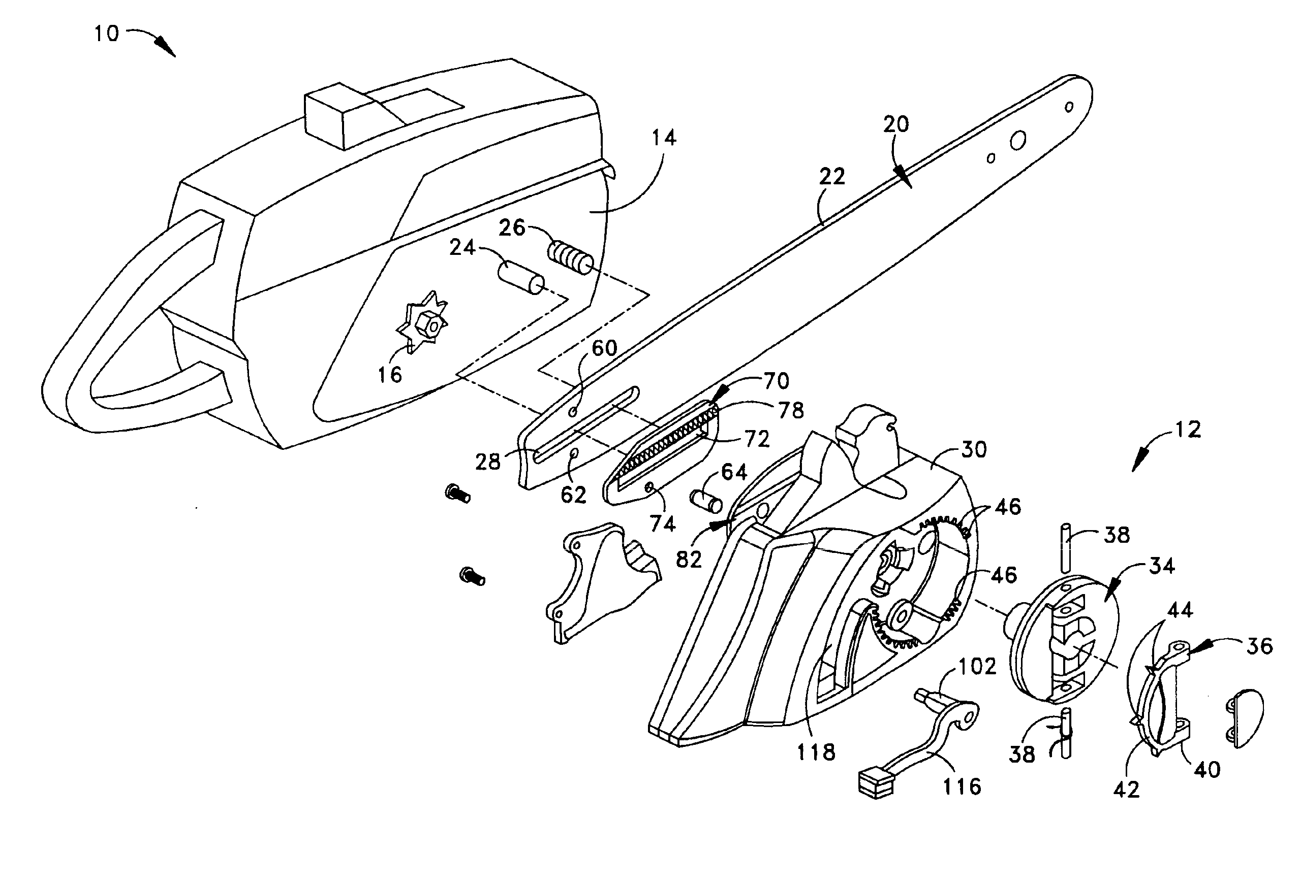
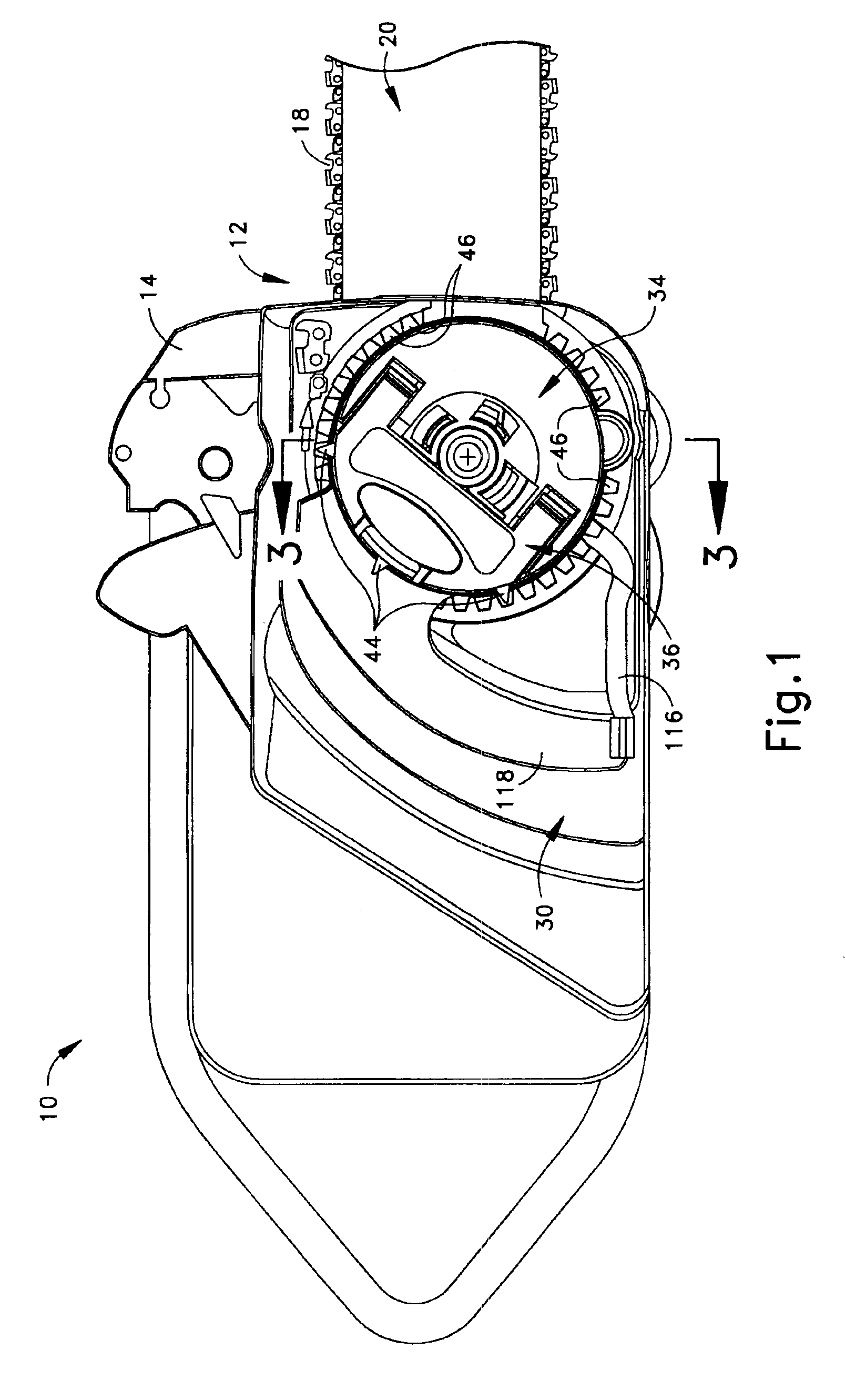
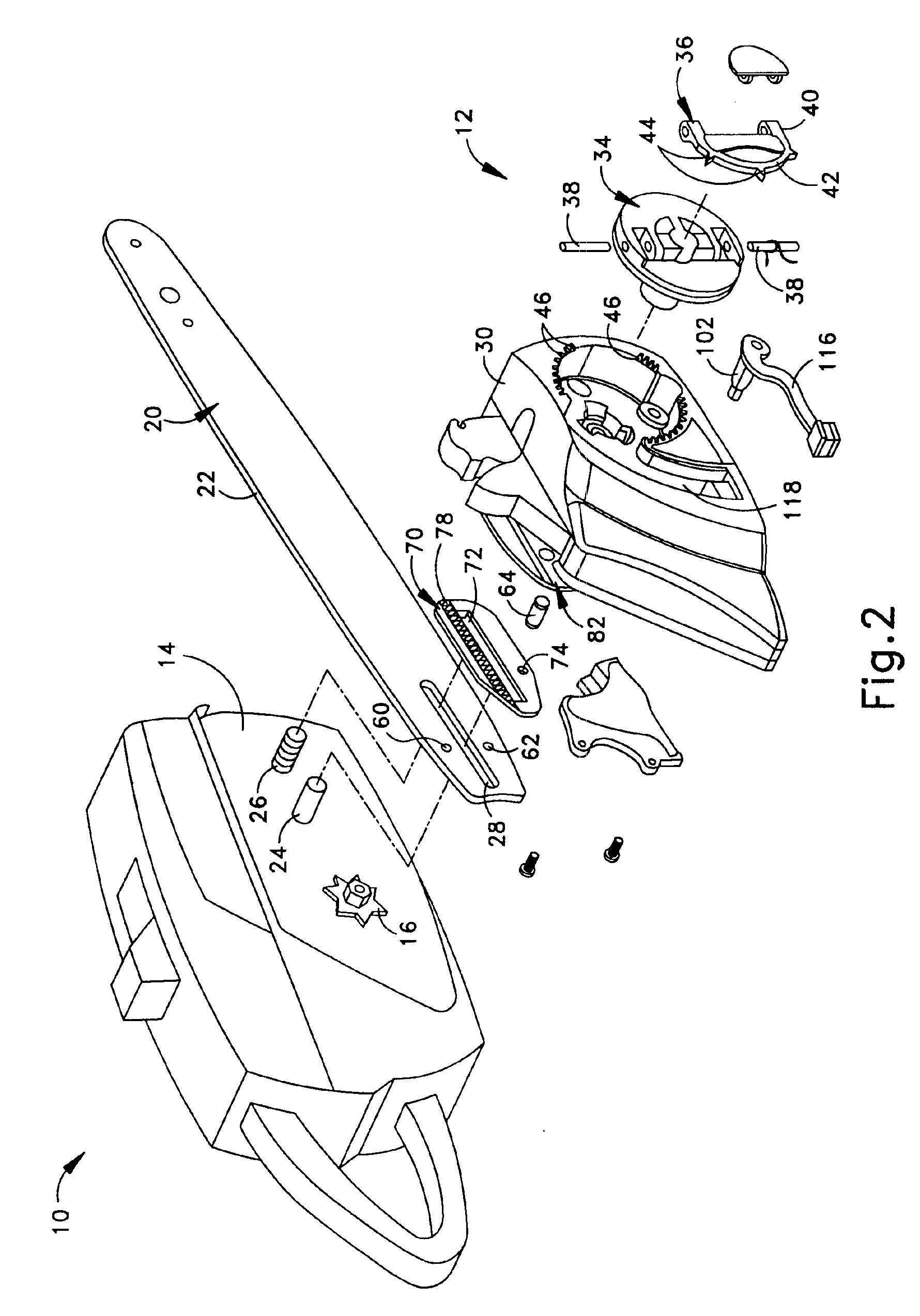
FIGS. 1 and 2 illustrate a chain saw 10 that includes an example of a chain tensioning mechanism 12 in accordance with the present invention. The chain saw 10 has an engine chassis 14 and an engine (not shown) located on the chassis. As will be appreciated the engine turns a drive sprocket 16 (FIG. 2) attached to a drive shaft of the engine. The drive sprocket 16 engages the links of an endless cutting chain 18 (FIG. 1) and propels the chain around a guide bar 20.

The guide bar 20 is of an elongated plate configuration with a channel or groove 22 (FIG. 2) around its periphery and an idler sprocket (not shown) at its distal end into which the links of the cutting chain 18 ride. Parallel pins or studs 24 and 26 affixed to the engine chassis 14 lie in a common generally horizontal plane and extend perpendicularly through an elongated horizontal slot 28 in the guide bar 20 with a sliding fit. The studs 24 and 26, align the guide bar 20 to the engine chassis 14 and, since the spacing betw...


PUM

PropertyMeasurementUnit
Tensionaaaaaaaaaa

Abstract

A tensioning mechanism for adjusting tension of a cutting chain in a chain saw. A rotatable knob operates with an engine chassis, clutch cover, and guide bar, whereby the knob may be rotated between a tightened position and loosened position, by which the guide bar is loosened and may be adjusted. The knob is provided with a knob handle, pivotally connected to the knob and pivotable between locked and unlocked positions. When the knob handle is in the locked position, at least one, but not all, of a plurality of handle engagement points engage with corresponding fixed engagement points that are fixed relative to the clutch cover. When the knob handle is in the unlocked position, the handle engagement points are disengaged from the fixed engagement points. Further, the engagement points are visible when the knob handle is in both locked and unlocked positions.

Description

FIELD OF THE INVENTIONThe invention relates to an arrangement that facilitates periodic tensioning of an endless cutting chain on a guide bar of a chain saw.BACKGROUND OF THE INVENTIONA cutting chain of a chain saw may become loose on a guide bar after some amount of use because of factors such as wear that results in elongation (i.e., stretch) of chain. Several saw constructions and associated methods exist to move the guide bar longitudinally away from a body and drive sprocket of the chain saw to take slack out of the cutting chain and ensure that links of the cutting chain remain snuggly seated in a peripheral channel in the guide bar.A number of the constructions and associated methods require an operator to loosen a retaining assembly using one or more separate tools, to grasp and move the guide bar longitudinally from the chassis to increase cutting chain tension, and then to retighten the retaining assembly to retain the guide bar. In other constructions and associated metho...

Claims


Application Information

Patent Timeline
IPC IPC(8): B27B17/14B27B17/00B23D57/02B27B13/00B27B13/08
CPCB27B17/14
Inventor FRANKE, JEFF S.
Owner HUSQVARNA OUTDOOR PROD INC
Why Eureka
Try Eureka