Rewinder apparatus and method

Inactive Publication Date: 2005-04-12
C G BRETTING MFG
View PDF258 Cites 63 Cited by
  • Summary
  • Abstract
  • Description
  • Claims
  • Application Information

AI Technical Summary

Benefits of technology

Because the web separator employed in the present invention moves toward the web at a velocity at least equal to that of the advancing web, the web is effectively separated upstream of the web separator, between the core and the web separator. Since the distance between the core and the web separator is controlled to be sh

Problems solved by technology

Such rewinders are generally limited in their ability to control the position and movement of cores through the rewinder nip, and therefore have limited control over web separation (where cores or core insertion devices perform web separation) and web transfer to new cores.
Although faster rewinding speeds are desired, a number of problems arise in conventional rewinders when their maximum

Method used


Image

  • Rewinder apparatus and method
  • Rewinder apparatus and method
  • Rewinder apparatus and method

Examples


Embodiment Construction

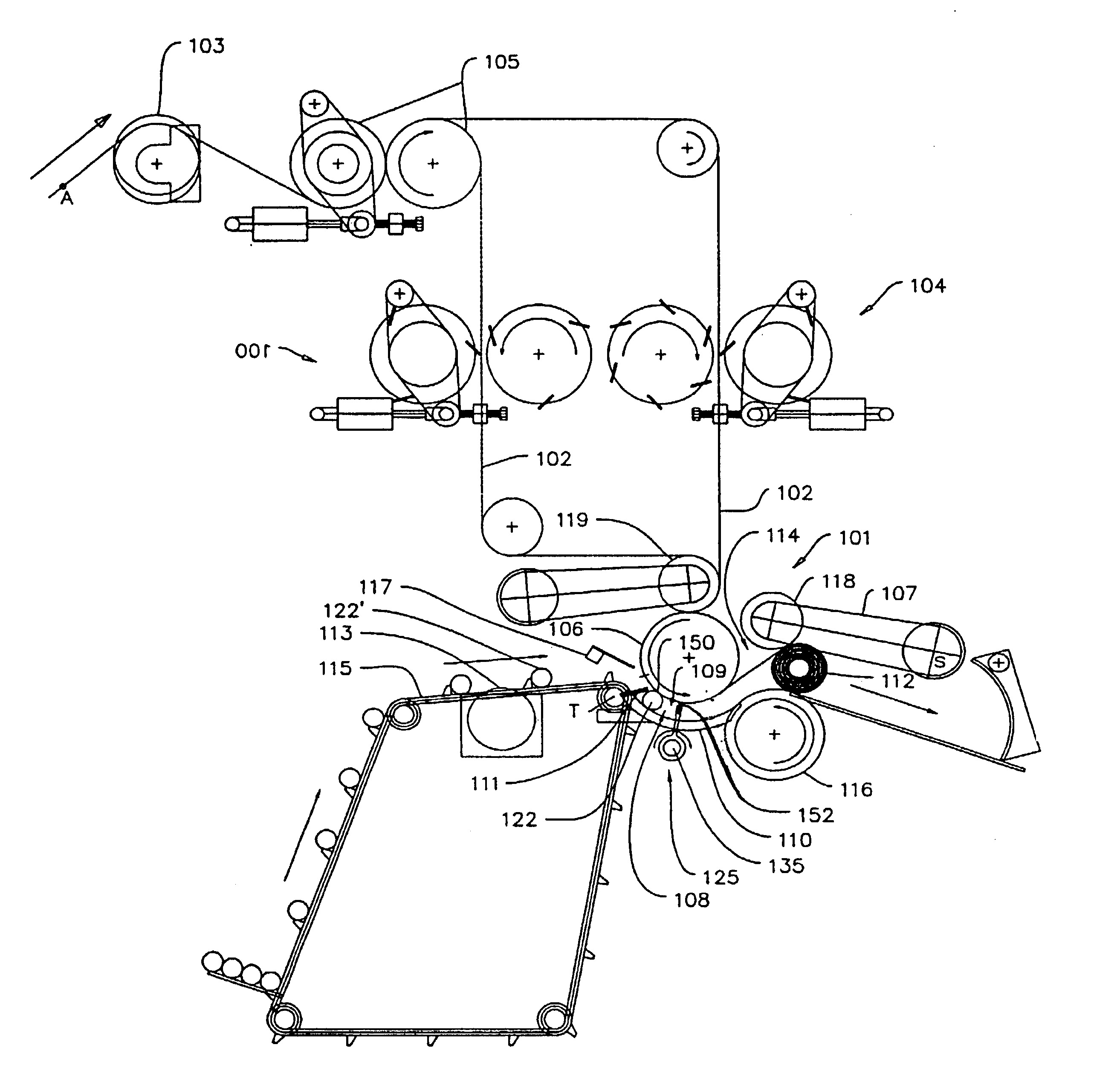
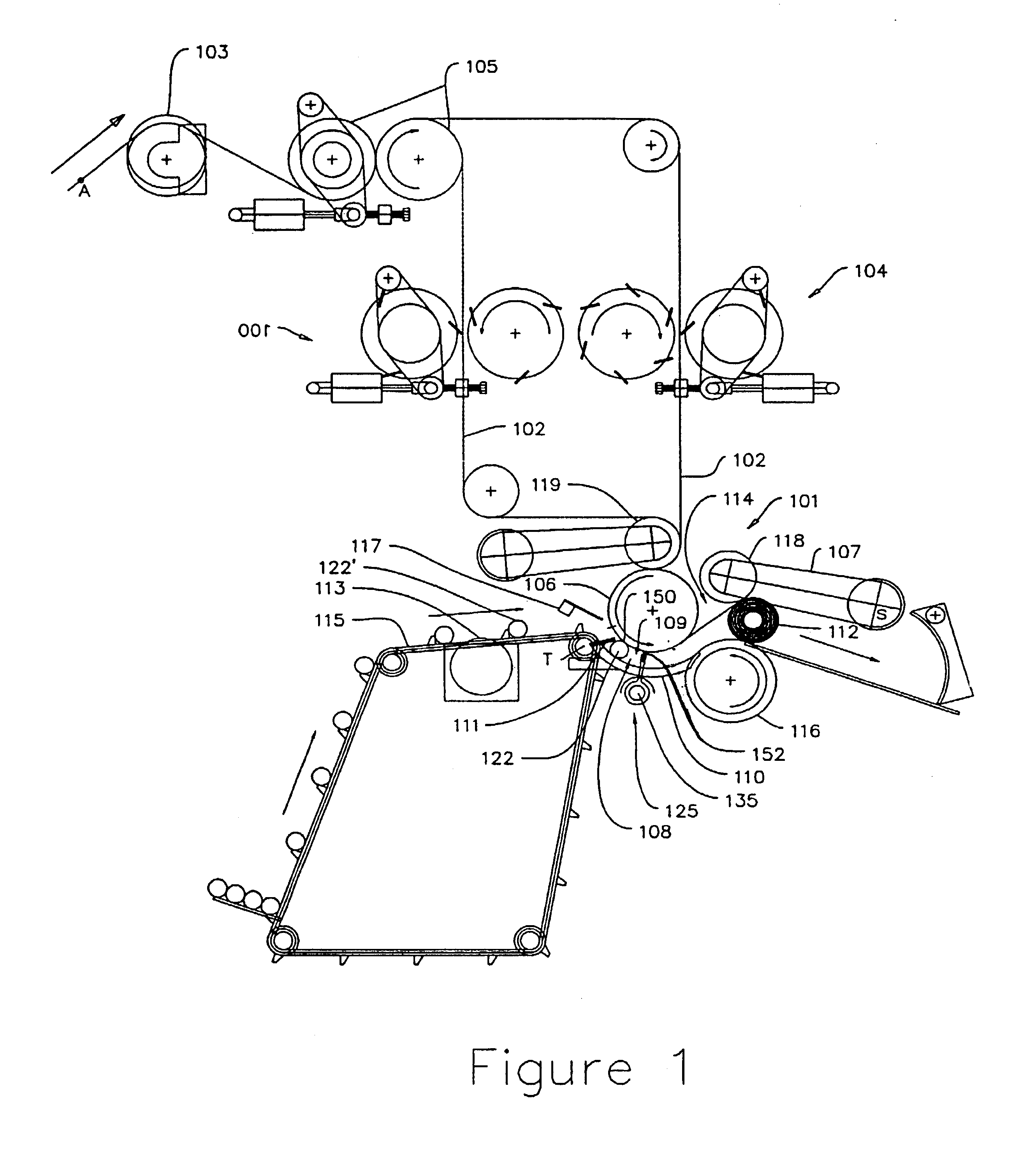
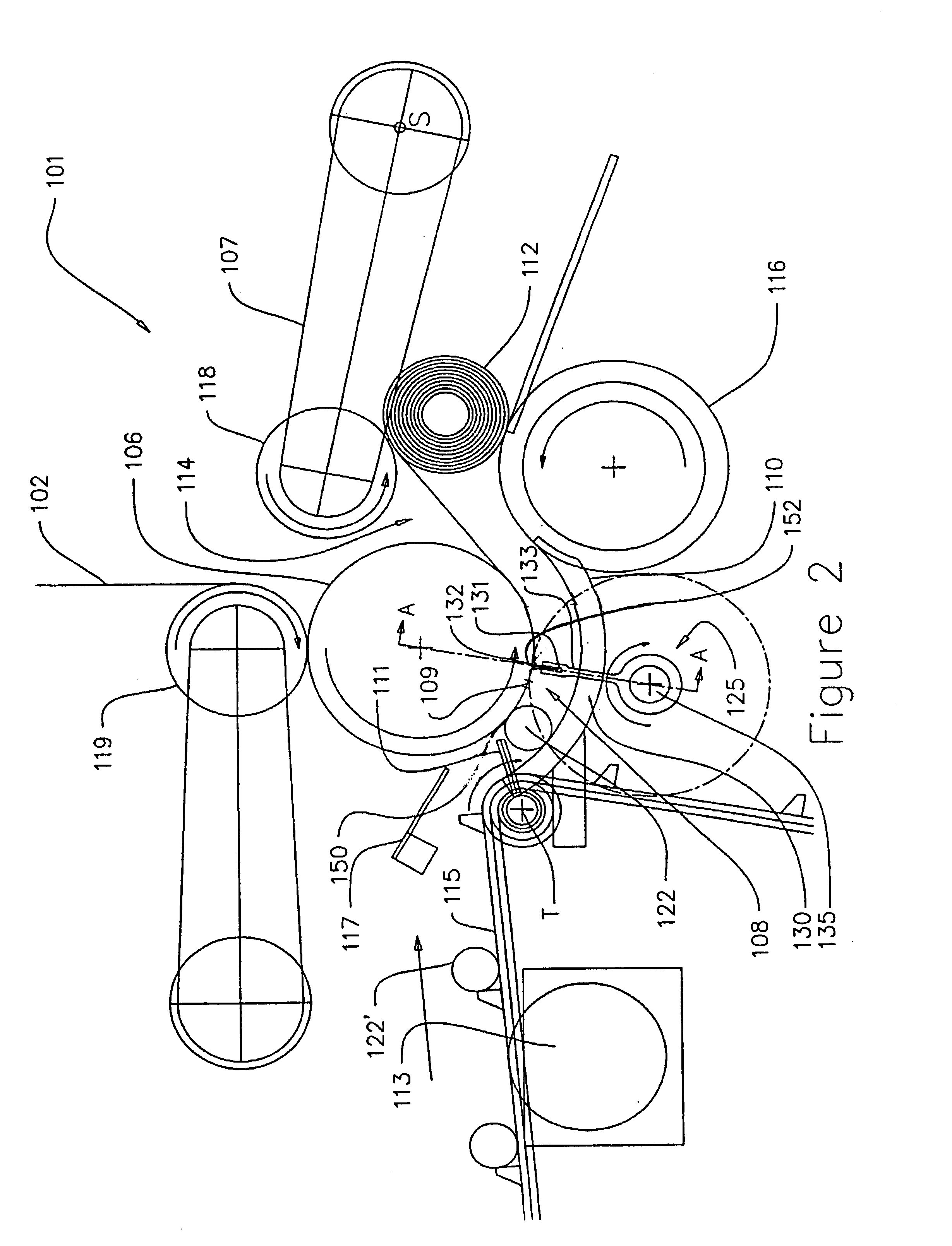
Referring to the figures, and more particularly to FIGS. 1 and 2, a rewinder constructed in accordance with some of the embodiments of the invention is shown generally at 100. The rewinder 100 includes a number of stations at which various functions are performed. In some of the embodiments, a web 102 of material enters the machine by passing over a bowed roll 103 for minimizing wrinkles in the web 102, then through a set of pull rolls 105 for controlling tension of the web 102. In some embodiments of the present invention, the web 102 then passes through one or more perforation stations 104. Any number of bowed rolls 103, pull rolls 105 or perforation stations 104 can be used without departing from the present invention. Furthermore, in some embodiments of the invention, no bowed roll 103, pull roll 105 or perforation station 104 is used. For the purpose of example only, one perforation station can be set up for the production of kitchen towels while another station can be set up f...


PUM

PropertyMeasurementUnit
Fractionaaaaaaaaaa
Fractionaaaaaaaaaa
Tensionaaaaaaaaaa

Abstract

A rewinder having a first winding roll that transports and supports the web, at least one core support plate that is curved for receiving and guiding cores adjacent the first winding roll, and a web separator adjacent the first winding roll and movable into pressing relationship with the web at a velocity at least equal to that of the web. The rewinder of exemplary embodiments winds a web of material a nip defined by the first winding roll, a second winding roll and a rider roll. The web separator of exemplary embodiments comprises a rotatable plurality of fingers that rotates about a common shaft. Because the web separator contacts the web moving at a velocity at least equal to that of the web, the web is effectively separated upstream of the web separator, between the core and the web separator.

Description

BACKGROUND OF THE INVENTIONSignificant developments in web rewinding have placed ever-increasing product output demands upon web rewinders. Conventional web rewinders are capable of winding a roll or “log” of material in seconds, with maximum winding speeds determined by the strength and other properties of the web and the core upon which the web is wound. Such rewinders are generally limited in their ability to control the position and movement of cores through the rewinder nip, and therefore have limited control over web separation (where cores or core insertion devices perform web separation) and web transfer to new cores. As used hereinafter and in the appended claims, the term “nip” refers to an area between two winding elements, such as between two winding rolls, a winding roll and conveyor belt, two facing conveyor belts, or other elements known to those skilled in the art used to rotate and wind a log therebetween. The nip can include an area disposed from the narrowest poin...

Claims


Application Information

Patent Timeline
IPC IPC(8): B65H19/30B65H19/22B65H19/26
CPCB65H19/2269B65H19/267B65H2408/235B65H2301/41812B65H2301/5152B65H2301/41447
Inventor BUTTERWORTH, TAD T.
Owner C G BRETTING MFG
Why Eureka
Try Eureka