Load path control for inflatable airbag

a technology of airbag cushion and load path, which is applied in the direction of vehicular safety arrangments, pedestrian/occupant safety arrangements, vehicle components, etc., can solve the problems of airbag cushion to tear out, and may be especially problematic in low clamp areas

Inactive Publication Date: 2005-04-12
AUTOLIV ASP INC
View PDF23 Cites 23 Cited by
  • Summary
  • Abstract
  • Description
  • Claims
  • Application Information

AI Technical Summary

Benefits of technology

The airbag cushion may be attached to the housing at attachment points within the attachment region. The attachment points allow a fastener such as a bolt to be passed through the attachment region to the housing. In general, the airbag cushion is secured to the housing at three or more attachment points. The attachment points may be evenly spaced around an inflation opening in the attachment region. The load controlling cutout may have a length equal to about 30% to about 90% of the distance between any two attachment points. It has been found that a load controlling cutout with a length equal to about two-thirds of the distance between two attachment points can shift the load force from a low clamp area to a high clamp area.

Problems solved by technology

Such tension can cause the airbag cushion to tear out from its sandwiched position between the retaining member and the housing.
The tearing may be especially problematic within low clamp areas.

Method used


Image

  • Load path control for inflatable airbag
  • Load path control for inflatable airbag
  • Load path control for inflatable airbag

Examples


Embodiment Construction

The presently preferred embodiments of the present invention will be best understood by reference to the drawings, wherein like parts are designated by like numerals throughout. It will be readily understood that the components of the present invention, as generally described and illustrated in the figures herein, could be arranged and designed in a wide variety of different configurations. Thus, the following more detailed description of the embodiments of the apparatus, system, and method of the present invention, as represented in FIGS. 1 through 6, is not intended to limit the scope of the invention, as claimed, but is merely representative of presently preferred embodiments of the invention.

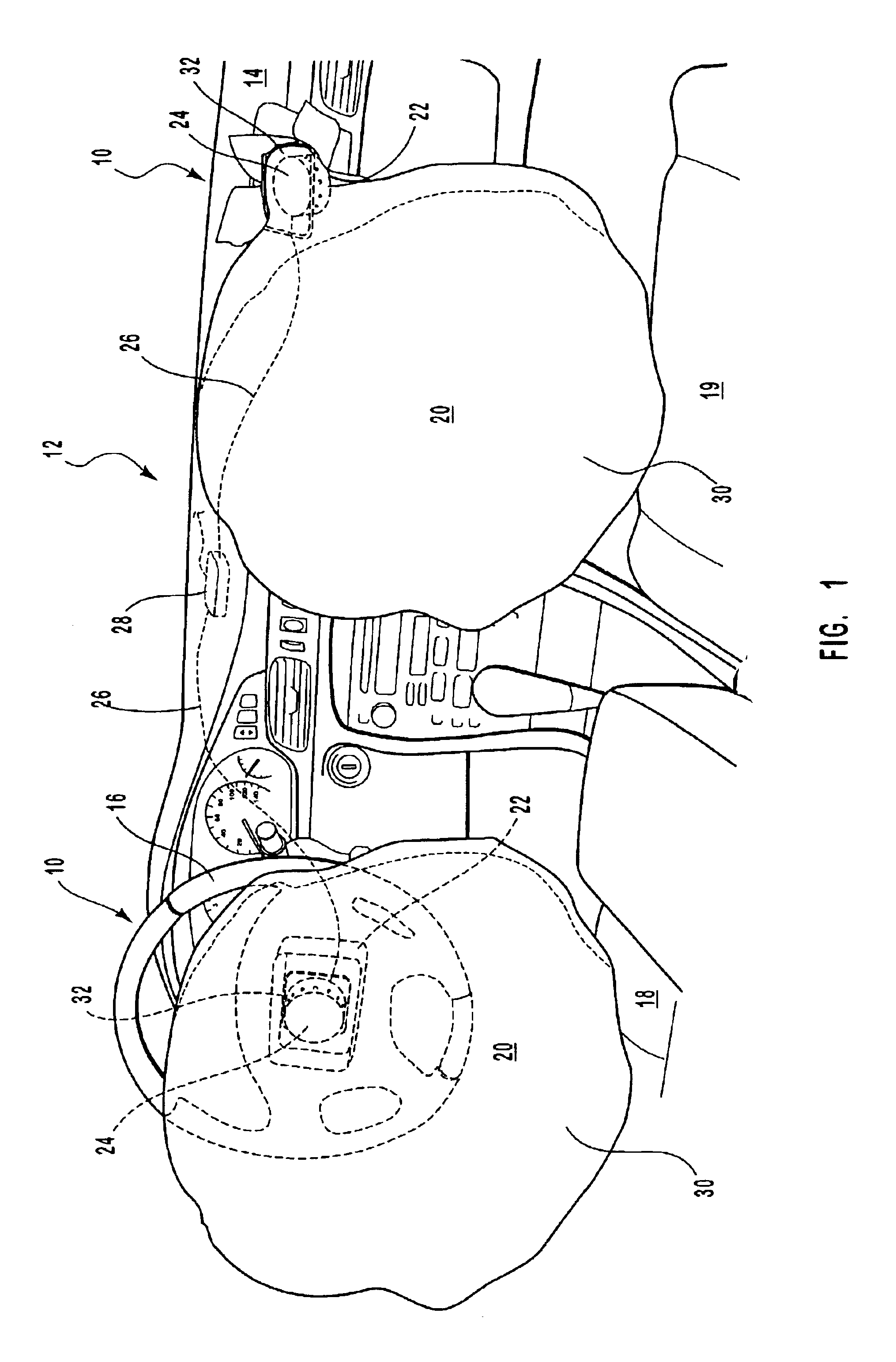
Referring to FIG. 1, two inflatable airbag modules 10 are depicted in the front seating area of a vehicle. The airbag modules 10 are shown installed within the dash board 14 adjacent the passenger's seat 19 and in the steering column adjacent the driver's seat 18. The airbag module 10 has an...


PUM


Abstract

An airbag cushion for protecting an occupant of a vehicle from an impact is presented. The airbag cushion has an inflatable region which inflates upon the reception of an inflation gas from an inflator. The airbag cushion is secured to a housing by a retaining member. The retaining member is configured to secure an attachment region of the airbag cushion to the housing by the use of fasteners which create a clamping force. The clamping force is highest adjacent the fasteners and is lowest at positions between the fasteners. Thus, a high clamp region is created adjacent the fasteners and a low clamp region is created at positions distant from the fasteners. As the airbag cushion is inflated, a load force puts tension on the attachment region of the airbag cushion potentially ripping the airbag cushion out from the low clamp regions. A load controlling cutout is positioned within the attachment region and between the fasteners. The load controlling cutout is configured to shift the load force the low clamp region to the high clamp region during inflation of the inflatable region.

Description

BACKGROUND OF THE INVENTION1. Field of the InventionThe present invention relates to vehicular airbag cushions. More specifically, the present invention relates to a load path control which redirects a load force in an inflating airbag cushion.2. Technical BackgroundInflatable safety restraint devices, or airbags modules, are now required by law to be installed in most new vehicles. Inflatable vehicle occupant safety restraint modules, or airbag modules, are mandatory on most new vehicles. Airbag modules commonly contain a collision sensor, an inflator, and an airbag cushion. In the event of an accident, a collision sensor such as an accelerometer, measures abnormal deceleration and triggers the inflator by means of an electronic signal. The inflator is generally a pyrotechnic device which produces gas. The inflator is connected to the airbag cushion and inflates the airbag cushion through an opening.Prior to inflation, the airbag cushions are housed in an uninflated and folded cond...

Claims


Application Information

Patent Timeline
Patent Type & Authority Patents(United States)
IPC IPC(8): B60R21/16B60R21/20B60R21/217B60R21/231
CPCB60R21/217B60R21/2342B60R21/23
Inventor ROSE, LARRY D.RUSSELL, MARC P.
Owner AUTOLIV ASP INC
Why Eureka
Try Eureka