Vehicular under-seat compartment mechanism

a seat-cushion and mechanism technology, applied in the field of seat-cushion mechanism, can solve the problems of inconvenience in publications, and achieve the effect of avoiding excessively fast rotation of seat-cushion and limited space in the vehicl

Inactive Publication Date: 2005-04-12
MITSUBISHI MOTORS CORP
View PDF41 Cites 54 Cited by
  • Summary
  • Abstract
  • Description
  • Claims
  • Application Information

AI Technical Summary

Benefits of technology

With the foregoing problems in view, it is a object of the present invention to provide a vehicular under-seat compartment mechanism in which space under a seat can be fully utilized by simple manner.
Partly because the seat-cushion is locked in a upright position by the lock mechanism, it is therefore possible to fully utilize the space under the seat.
Because the unlock mechanism is equipped with the lock mechanism for unlocking the locking by the lock mechanism, further, the unlock strap is disposed at the rear end of the seat-cushion. It is therefore possible to flip up the seat-cushion with a simple action of pulling up the unlocking strap by a user so that the seat-cushion is rotated to the upright position. Further, the user is required to take two actions; the first action is pulling the unlocking strap and the second action is pivotally moving the seat-cushion to the horizontal position. With this arrangement, it is possible to avoid excessively fast rotation of the seat-cushion therefore the user can rotate the seat-cushion to the horizontal position at a preferable speed even if the user disregards the motion speed of the seat-cushion.
Partly because, the lock pin selectably fits into the first slot or the second slot of the cam. Thus, it is possible to avoid the user sitting on the seat cushion in an intermediate position between the upright position and the horizontal position. Namely, the seat-cushion cannot be fixed in such an intermediate position, and the seat-cushion 12 is raised perpendicularly in the upright position. The user should therefore be easily aware that it is not possible to sit on a seat in the upright position, and that sea-cushion should be rotated before sitting is possible. Further, the unlock strap and the cam is linked by the wire, it is therefore possible to avoid limitation of arrangement of the location of the unlock strap so that the unlock strap is disposed at a position useful for the user.
Partly because, the inner lid is held in the opening position by the inner lid strap hooking onto the seat-hook attached on the back face of the seat-cushion. It is therefore possible to be placed even long and / or bulky objects in the compartment. It is also possible to become more convenient for uses in such a way that the seat-hook can be used as a hook for hooking, for example, the handle of a bag.
Because the extra wall is higher than the inner lid in the closed position, it is therefore possible to avoid rolling down an object, which is placed on the inner lid, onto the floor.

Problems solved by technology

However, the techniques of the above Japanese patent publications entail some inconvenience because the seat cushion 106 cannot remain upright in an open position after the user rotates the seat cushion 106, as the hinge 102 simply provides an axis on which rotate the seat cushion 106 with respect to the seat frame 108.
Therefore the unstable seat cushion 106 may press or lean on the oversized object, sticking out from inside the container 104, causing damage.

Method used


Image

  • Vehicular under-seat compartment mechanism
  • Vehicular under-seat compartment mechanism
  • Vehicular under-seat compartment mechanism

Examples


Embodiment Construction

An embodiment of the present invention will now be described with reference to the accompanying drawings FIGS. 1 through 7.

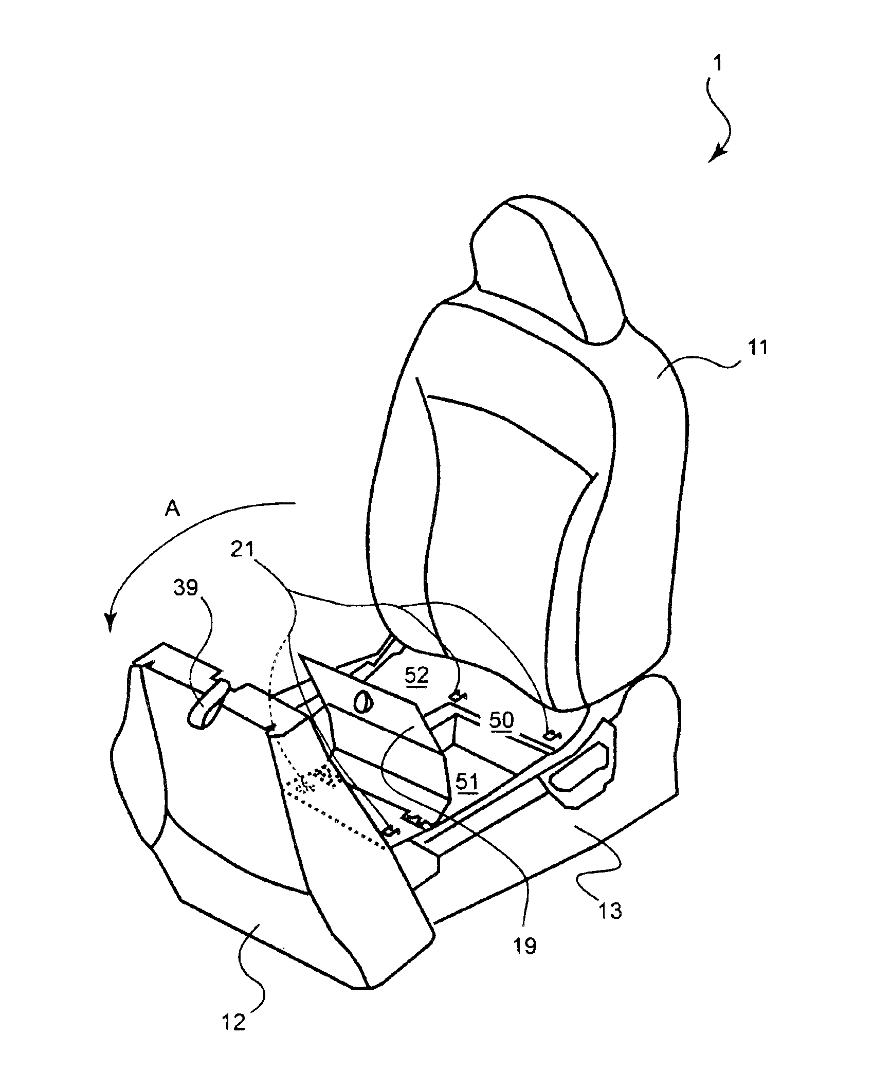
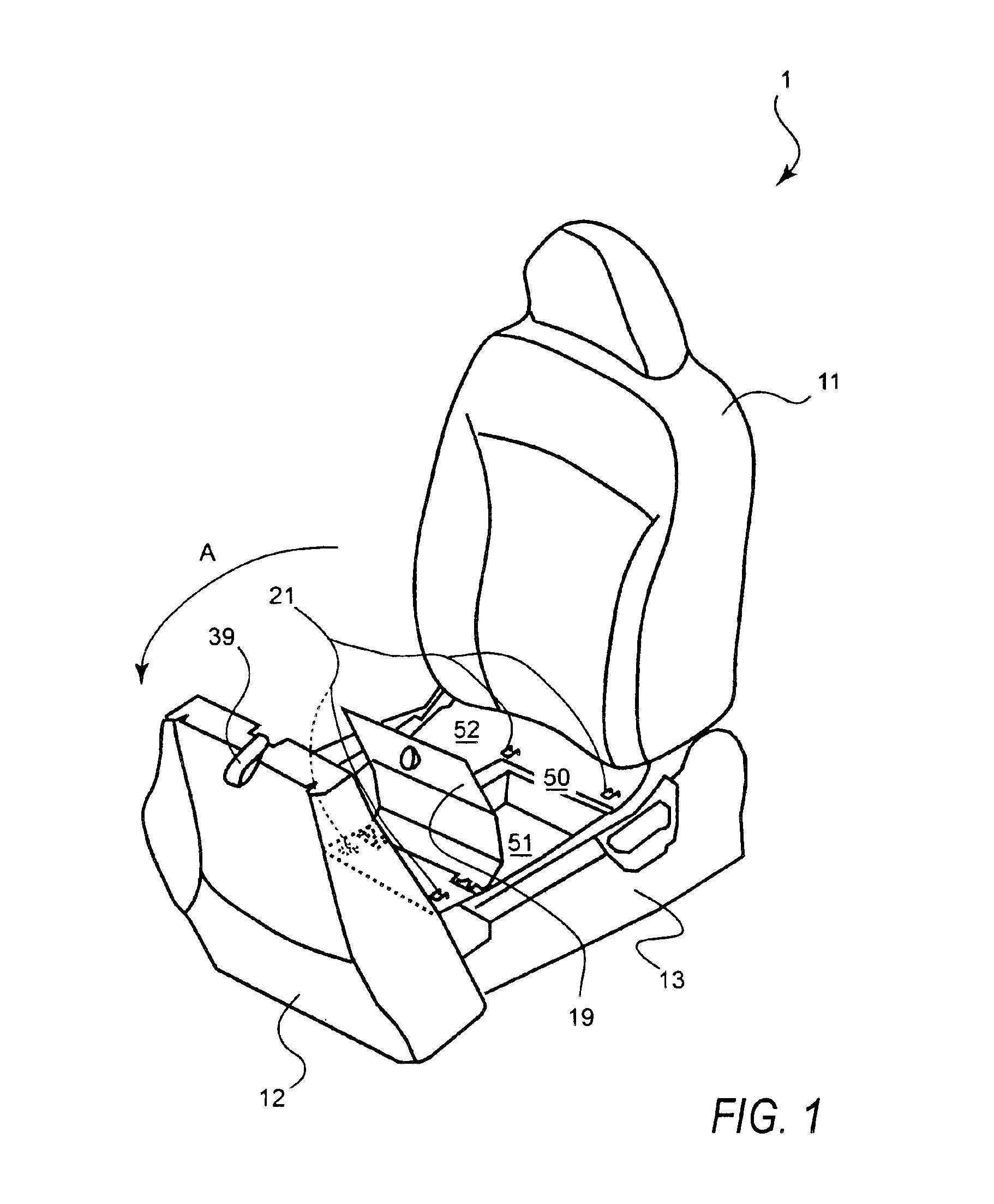
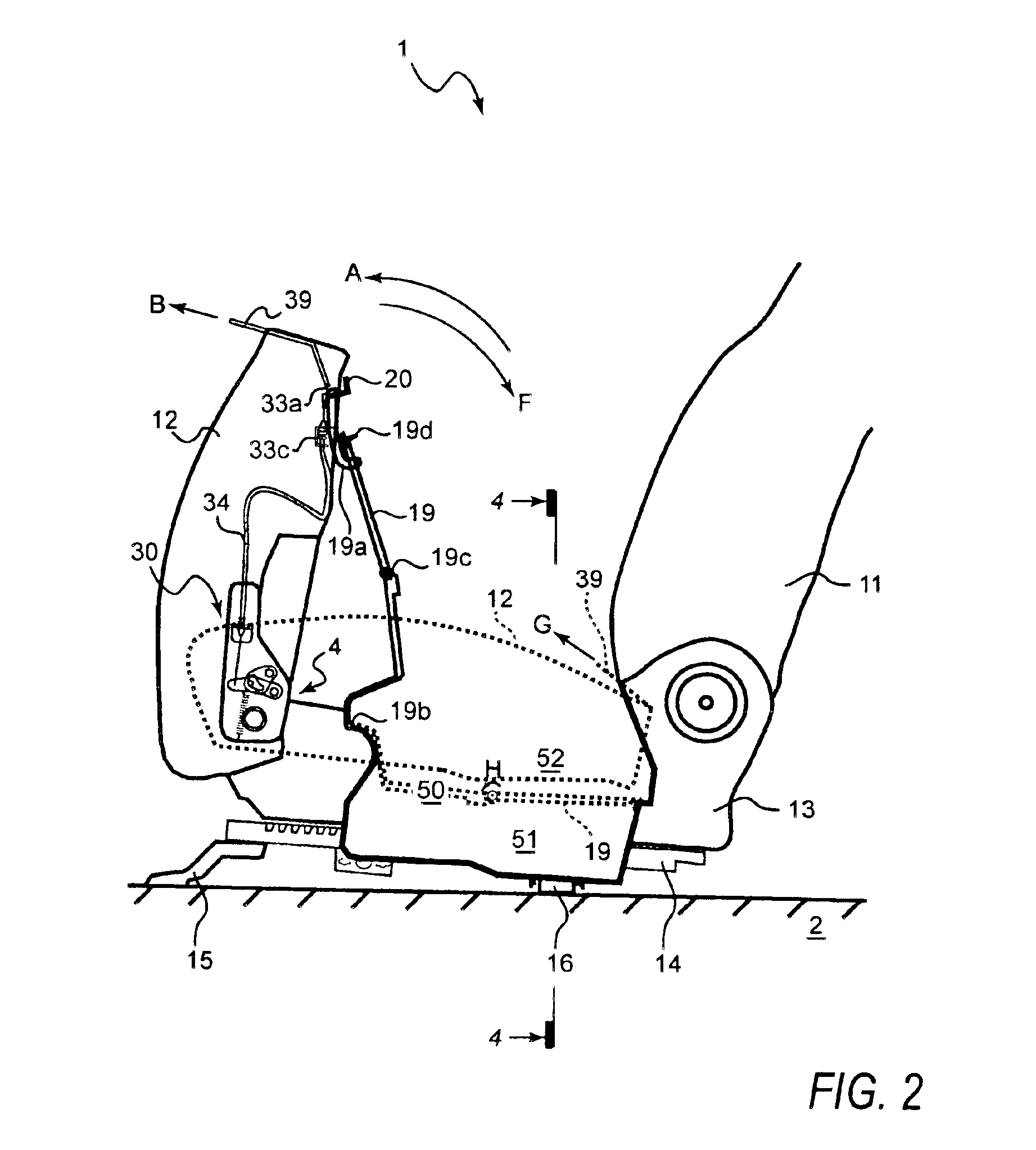
FIG. 1 is a perspective view showing a vehicular under-seat compartment mechanism; FIG. 2 is a schematic side view showing the vehicular under-seat compartment mechanism when a seat-cushion is in a upright position;

FIG. 3 is a detailed view of a lock mechanism when the seat-cushion is in the upright position; FIG. 4 is a schematic sectional view of the seat mechanism taken along the lines 4—4 of FIG. 2; FIG. 5 is a detailed view showing a lock mechanism when the seat-cushion is between the upright position and a horizontal position; FIG. 6 is a detailed view showing a lock mechanism when the seat-cushion is in the horizontal position; and each of FIG. 7(A), FIG. 7(B), and FIG. 7(C) is a schematic view showing examples of how an object is placed in the compartment.

As shown in FIG. 1, a seat 1 mainly includes a seat-back 11, a seat-cushion 12 and a seat-bottom 13....


PUM


Abstract

To utilize limited space in a vehicle cabin, a vehicular under-seat compartment mechanism includes a hinge mechanism, a compartment and a lock mechanism. The hinge mechanism interconnects a seat-frame and a seat-cushion in such a manner that the seat-cushion is pivotally rotatable with respect to the seat-frame. The compartment is disposed in the under-seat space under the seat and is formed an opening upwardly. The lock mechanism, integrated with the hinge mechanism, locks the seat-cushion at an upright position, at which the seat-cushion is pivotally flipped up about the hinge mechanism so that the compartment is accessible.

Description

BACKGROUND OF THE INVENTION1. Field of the InventionThe present invention relates to a seat compartment mechanism. More particularly the invention concerns an improvement of the seat compartment mechanism for practically using a space under a seat in a vehicle.2. Description of Related ArtTo utilize space in a vehicle cabin, techniques such as those of the following patent publications disclose disposing a container under a passenger seat. The disclosed techniques will be discussed with reference to accompanying drawing FIG. 8Japanese Patent Publications#1: 3070810#2: 3070811A conventional seat 101 mainly comprises a seat-back 103, a seat cushion 106 and a seat frame 108. The seat cushion 106 is pivotally connected with a front edge of the seat frame 108 via a hinge 102. The seat cushion 106 has a latch mechanism at a rear end of the seat cushion 106 for latching the seat cushion 106 with respect to the seat frame 108 at a position that a user can sit down on the seat cushion 106.Be...

Claims


Application Information

Patent Timeline
Patent Type & Authority Patents(United States)
IPC IPC(8): B60N2/30B60R7/04B60N2/90
CPCB60R7/043B60N2/305B60R7/04
Inventor MIZUNO, KOJIMORINISHI, YASUJIKUTOMI, SHINGOOGINO, TAKASHI
Owner MITSUBISHI MOTORS CORP
Why Eureka
Try Eureka