Pattern formation method and substrate manufacturing apparatus

a substrate manufacturing and pattern technology, applied in the direction of conductive pattern formation, coating, printing, etc., can solve the problem of inability to form patterns merely, and achieve the effect of simple manufacturing and low cos

Inactive Publication Date: 2005-04-12
SEIKO EPSON CORP
View PDF28 Cites 44 Cited by
  • Summary
  • Abstract
  • Description
  • Claims
  • Application Information

AI Technical Summary

Benefits of technology

It should be noted that unlimited commercial demand exists for processes in which patterns on the order of micrometers (which do not quite reach the scale of VLSI or other such fine patterns) could be manufactured simply, inexpensively, and without the use of plants or other equipment.
Specifically, a first object of the present invention is to provide a method that allows patterns to be formed by enabling treatments to be performed before a fluid is ejected onto a substrate, and to provide a manufacturing apparatus therefor.
A second object of the present invention is to provide a method that allows patterns to be formed by enabling treatments to be performed after a fluid has been ejected onto a substrate, and to provide a manufacturing apparatus therefor.
A third object of the present invention is to provide a method that allows patterns to be formed by enabling treatments to be performed the moment a fluid is ejected onto a substrate, and to provide a manufacturing apparatus therefor.

Problems solved by technology

It is, however, impossible to form patterns merely by configuring the system such that a fluid can be ejected from an ink-jet print head.

Method used


Image

  • Pattern formation method and substrate manufacturing apparatus
  • Pattern formation method and substrate manufacturing apparatus
  • Pattern formation method and substrate manufacturing apparatus

Examples


embodiment 1

Embodiment 1 of the present invention relates to a treatment that exerts action (reduction in solubility) on the fluid, and is primarily used in the first and second arrangements described above.

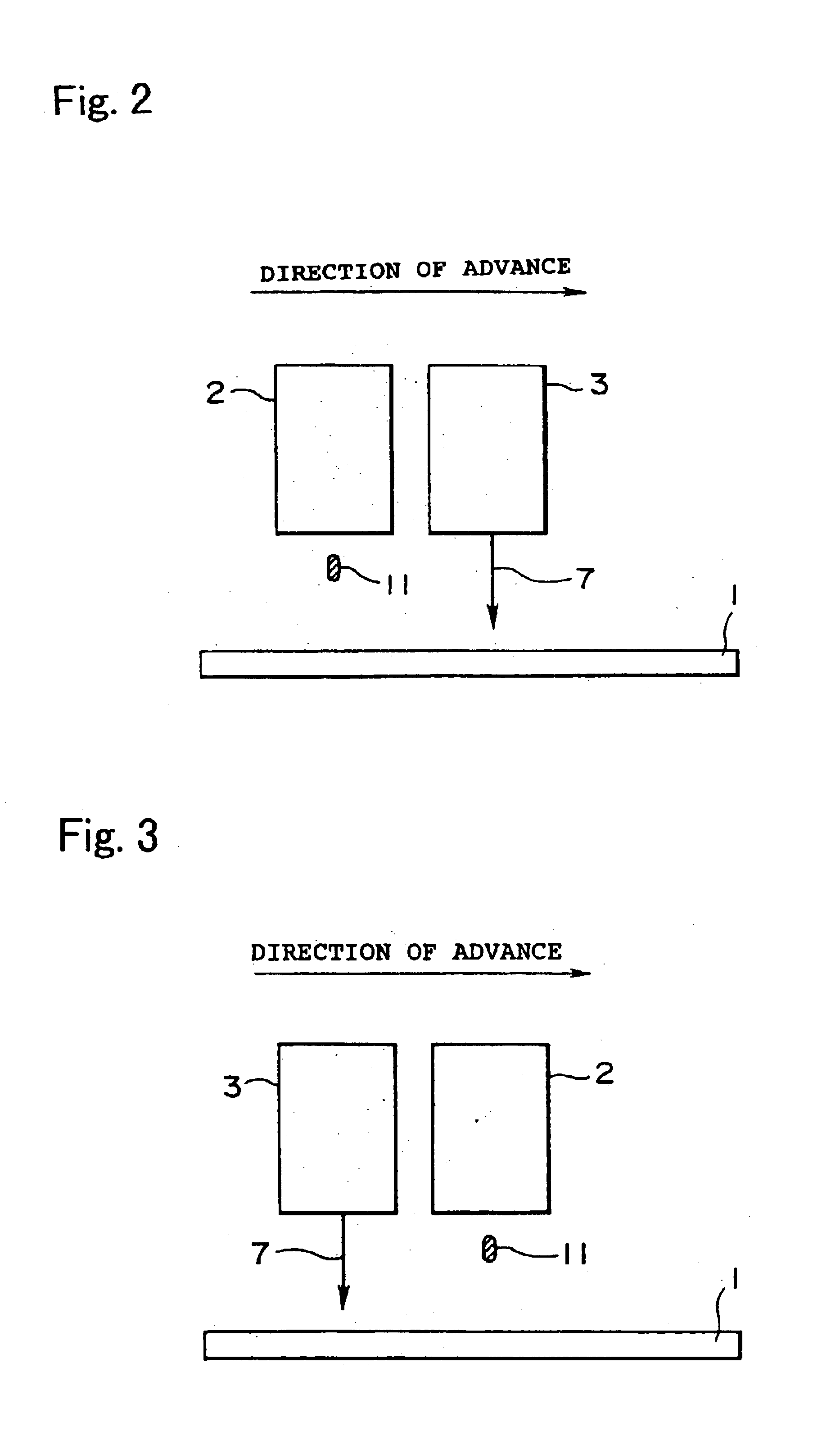
FIG. 5 is a side view illustrating the treatment concept of Embodiment 1. The treatment apparatus 301 of Embodiment 1 is configured such that a treatment 701 for lowering the solubility of substances admixed into the fluid and precipitating these substances as solids can be applied to the substrate 1, before a droplet 11 is ejected. A treatment in which a hot-air blast, laser irradiation, lamp irradiation, or the like is performed to vaporize the solvent components of the fluid can be suggested as such a treatment. Although the drawing depicts the structure utilized for the first arrangement, the treatment apparatus 301 can be disposed behind the ink-jet print head 2 in the direction of advance when the structure is utilized for the second arrangement.

When hot air is to be blown, the treatme...

embodiment 2

Embodiment 2 of the present invention relates to a treatment that induces chemical action (chemical reaction) in the fluid, and is primarily used in the first and second arrangements described above.

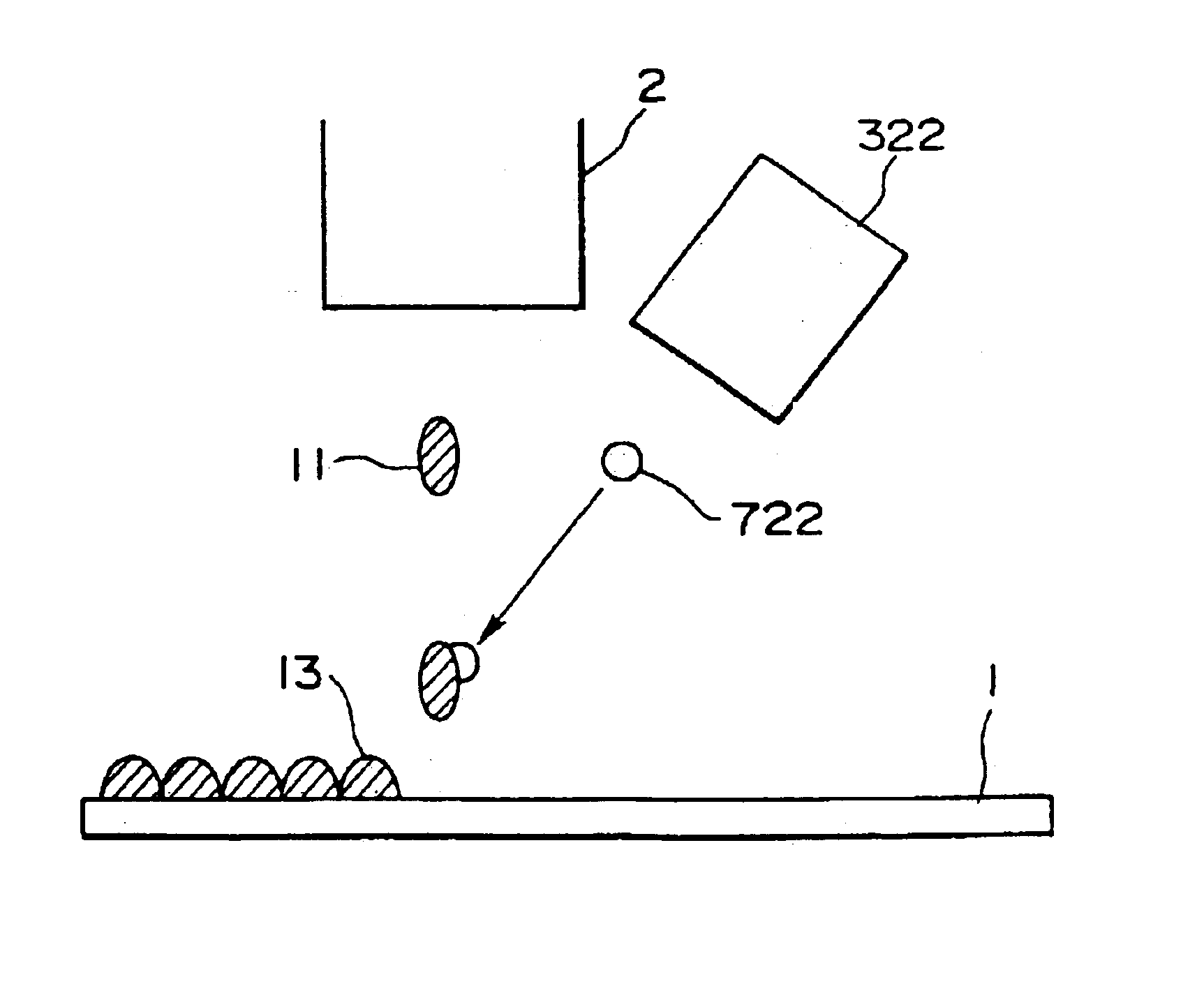
FIG. 6 is a side view illustrating the treatment concept of Embodiment 2. The treatment apparatus 302 of Embodiment 2 is configured such that a reaction solution 702 capable of breaking up a disperse system or initiating a chemical reaction in the fluid is ejected on the substrate 1 before the fluid 10 is ejected. The same structure as that of the ink-jet print head 2 should preferably be used as the treatment apparatus 302. This is because substantially the same amount of reaction solution as that of the fluid droplets 11 can be ejected in a controlled manner. Although the drawing depicts the structure utilized for the first arrangement, the treatment apparatus 302 is disposed behind the ink-jet print head 2 in the direction of advance when the structure is utilized for the second arran...

embodiment 3

Embodiment 3 of the present invention relates to a treatment for improving the affinity of the substrate as a physical-chemical action, and is primarily used in the first arrangement described above.

FIG. 7 is a plan view illustrating the treatment concept of Embodiment 3. The treatment apparatus 303 of Embodiment 4 is configured such that the pattern-forming region of the substrate 1 can be surface-modified to achieve affinity for the fluid 10 before this fluid has been ejected onto the substrate.

The following methods can be used as surface modification treatments aimed at achieving affinity when the fluid contains polar molecules (moisture and the like): methods for applying silane coupling agents; methods for forming aluminum oxide, silica, and other porous films; and methods for performing reverse sputtering in argon or the like; as well as corona ejection treatments, plasma treatments, ultraviolet irradiation treatments, ozone treatments, degreasing treatments, and various other...


PUM


Abstract

A pattern formation method for discharging a prescribed fluid onto a substrate form an ink-jet head and forming an arbitrary pattern. The method including the steps of discharging the fluid onto the substrate from an ink jet head and defining a pattern-forming region by subjecting the substrate to a specific treatment to prevent the fluid from spreading. The pattern forming region is formed after the fluid has been ejected so that the arbitrary pattern is formed in the fluid corresponding to the pattern-forming region. The treatment is one in which banks for preventing the fluid from flowing out are formed around the pattern-forming region. The method also includes removing the banks following the formation of the pattern.

Description

BACKGROUND OF THE INVENTION1. Field of the InventionThe present invention relates to a commercial use of an ink-jet print head, and more particularly to a manufacturing technique for forming arbitrary patterns with the aid of an ink-jet system.2. Description of the Related ArtSubstrates used in semiconductor processes or the like are formed from silicon and the like. Lithographic techniques and the like have been used in the past for manufacturing integrated circuits and the like from such silicon substrates.A characteristic feature of the lithographic techniques is that a photosensitive material called resist is applied thinly to a silicon wafer, and an integrated circuit pattern produced by photolithography on a dry glass plate is transferred by being printed with the aid of light. Ions or the like are implanted into the transferred resist pattern, gradually forming wiring patterns or elements.Because photolithography, resist application, exposure, development, and other steps are...

Claims


Application Information

Patent Timeline
Patent Type & Authority Patents(United States)
IPC IPC(8): H01L21/00H01L21/70H01L51/40H01L21/768H01L51/05H05K3/12B41J2/01H01L21/3205H01L51/00
CPCH01L21/288H01L21/6715H01L21/768H01L51/0005H05K3/125H01L21/76838H01L27/1292H10K71/135
Inventor KIGUCHI, HIROSHIFUKUSHIMA, HITOSHINEBASHI, SATOSHISHIMODA, TATSUYA
Owner SEIKO EPSON CORP
Why Eureka
Try Eureka