
Connector plug

Inactive Publication Date: 2006-06-08
WOBBEN ALOYS
View PDF4 Cites 5 Cited by
  • Summary
  • Abstract
  • Description
  • Claims
  • Application Information

AI Technical Summary

Benefits of technology

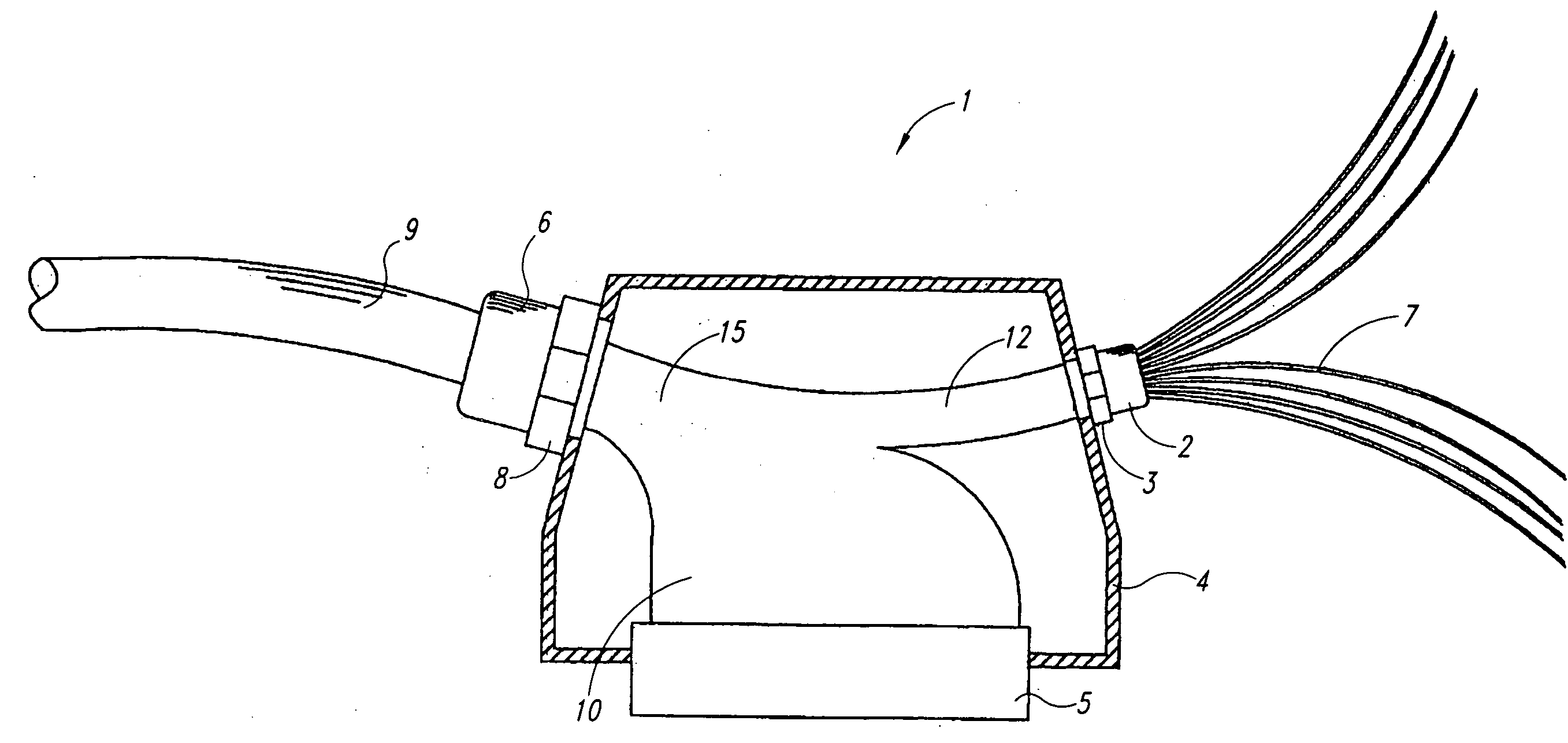
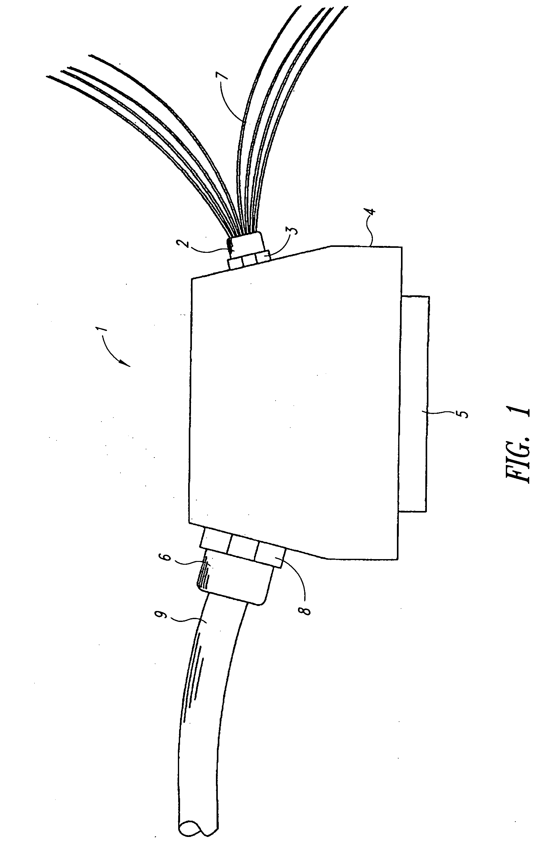
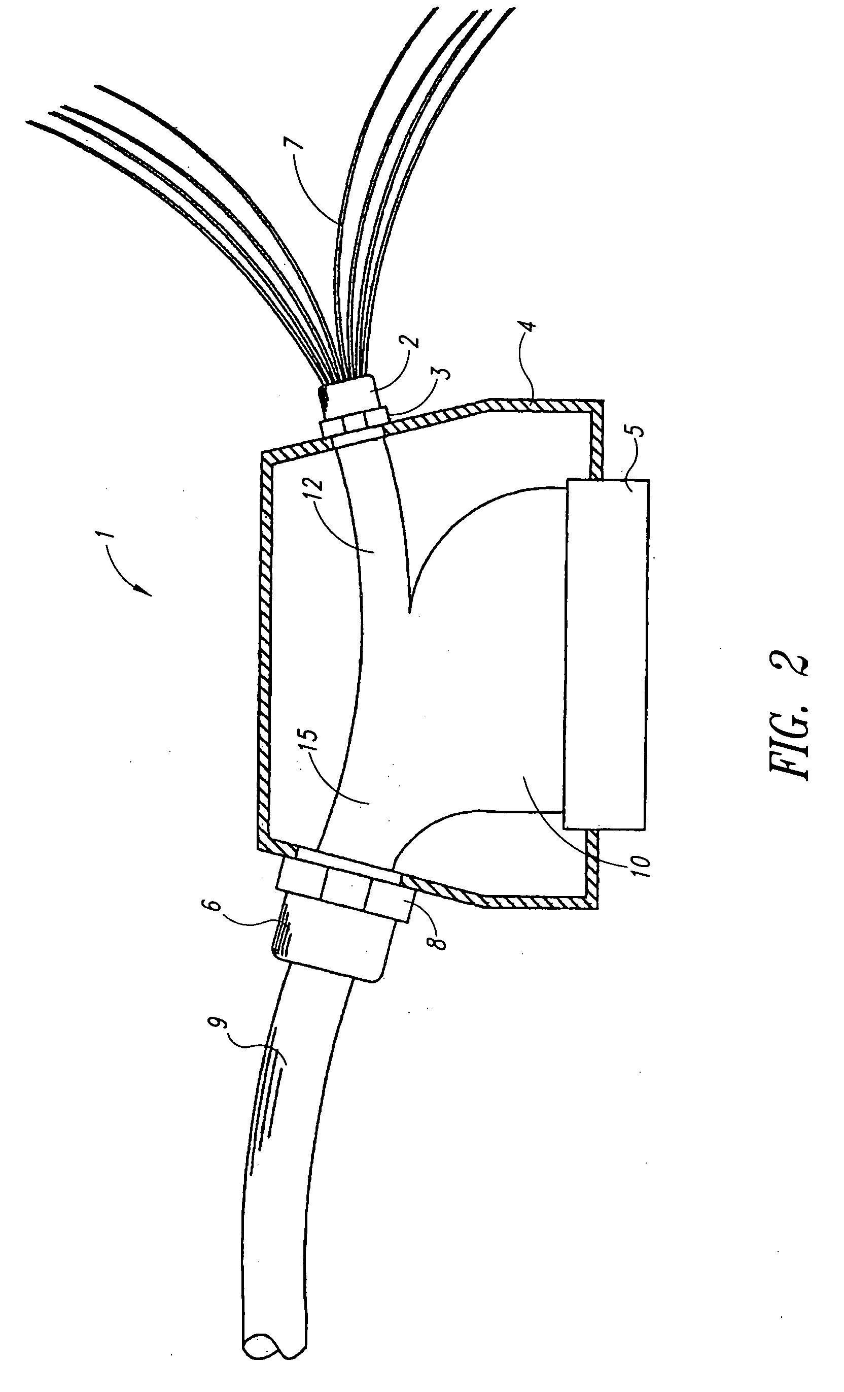
[0022] The teaching of the invention has the advantage that cables containing conductors that operate according to different physical principles can be fed into the plug connector and that only galvanic conductors, for example, are connected to a suitably configured contact insert. Accordingly, said contact insert can be manufactured and provided simply and inexpensively, unlike contact inserts for connecting different physical systems. For example, it is possible in this way to connect galvanic conductors in the plug connection 5 and to simply feed the optical conductors 7 back out through a standard bushing 2, connect them in a separate plug connection designed for optical waveguides, and by this means connect them to a suitable mating piece.

Problems solved by technology

However, a particular disadvantage of this known solution is that it can only be used in setups in which the mating contacts are likewise configured in such a way that the respective conductors can also be connected to their matching conductors.

Method used


Image

  • Connector plug
  • Connector plug
  • Connector plug

Examples


Embodiment Construction

[0012] The invention proposes that, in a plug connector of the kind specified, a second cable bushing is provided on a plug housing such that, even though the first cable bushing of the plug connector receives two different cables, the second cable bushing nevertheless receives only one of the two cables (or additional cables).

[0013] The second cable bushing is preferably provided on a different side of the plug connector than the plug contact, so that the plug contact can be a standard plug contact (contact pin or other standardized contacts), for example, and that another conductor, for example, can be fed through the second cable bushing to a desired position.

[0014] Plug connectors according to the invention can be used, in particular, wherever a current, e.g., a control current, is transferred by a copper cable, on the one hand, and where waveguides can be also be used to transfer data, on the other hand, for example for high-speed transfer of data signals for controlling and / ...


PUM


Abstract

The present invention provides a plug connector in order to extend the uses of the plug connector. A plug connector comprising a plug housing and a first bushing for a cable having at least a first and second conductor, a contact insert for the first conductor integrated in said housing, means for fixating the cable in the bushing area, and a second cable bushing, characterized in that the second conductor is fed out of the housing through the second cable bushing.

Description

BACKGROUND OF THE INVENTION [0001] 1. Field of the Invention [0002] The invention relates to a plug connector for both optical and electrical cables to pass there through. [0003] 2. Description of the Related Art [0004] A plug connector of this kind is known from DE 195 26 267 A1, for example. [0005] In said known plug connector, a copper conductor and an optical waveguide are jointly fed through a common cable gland into a plug housing, and the different cables are connected to corresponding contact inserts. The copper conductor comprised of two copper leads is thus connected to the standard earthed contacts as connectors, whereas the optical waveguide is connected to an optical waveguide connector. However, a particular disadvantage of this known solution is that it can only be used in setups in which the mating contacts are likewise configured in such a way that the respective conductors can also be connected to their matching conductors. [0006] A plug connector housing with two ...

Claims


Application Information

Patent Timeline
Patent Type & Authority Applications(United States)
IPC IPC(8): H01R13/58G02B6/38G02B6/44H01R13/46H01R13/516H02G15/117
CPCG02B6/3817G02B6/4476H01R13/516H02G15/117H01R13/46
Inventor WOBBEN, ALOYS
Owner WOBBEN ALOYS
Learn More