Optical fiber cross-connect with a connection block, an alignment block and a handling device

a technology of optical fiber and connection block, which is applied in the direction of optics, optical light guides, instruments, etc., can solve the problems of affecting the affecting the operation of the optical cross-connecting apparatus, so as to achieve the effect of ensuring high reliability of optical cross-connecting, eliminating entanglement, and reducing cos

Inactive Publication Date: 2005-04-12
NIPPON TELEGRAPH & TELEPHONE CORP
View PDF8 Cites 18 Cited by
  • Summary
  • Abstract
  • Description
  • Claims
  • Application Information

AI Technical Summary

Benefits of technology

A first object of the present invention is to provide an optical connector plug, an optical connector plug connecting method, an optical fiber cross-connection apparatus, an optical fiber cord retracting method, an optical fiber cord retraction device, and an optical connector plug alignment block, all of which can be applied to an optical connection at a specified position, as in an APC optical connector plug, secure high reliability for optical cross-connecting, eliminate entanglement during cord windup, and reduce cost.

Problems solved by technology

This makes it difficult to apply the conventional structure as is to the APC optical connector plugs.
Further, when an optical connector plug is inserted into the optical adapter with the plug attitude rotated from a connection attitude in which the optical connector plug can be connected or when the optical connector plug inserted in the optical adapter is applied a rotating force, expected optical characteristics, such as a desired insertion loss, may not be obtained.
There is another problem with the conventional optical fiber cross-connection apparatus.
When an optical connector plug is pulled out from the optical adapter of the connection block by a handling device and its optical fiber cord is retracted by the optical fiber cord retraction device to be accommodated in the redundant cord storage unit, a flange of the optical connector plug may get entangled and caught by other cords, rendering a normal retraction of the cord impossible.
Thus, the optical fiber cords may develop persisting physical distortions, such as twists and bends.
Therefore, if the optical fiber cords are moved forward and backward by holding them between the retraction roller and idle roller, they may get dislocated from between the retraction roller and idle roller due to their physical distortions, such as twists and bends.
Further, depending on a distance between the provided positions of the optical connector plug alignment block and the redundant cord storage unit, the optical fiber cords that are being retracted by the optical fiber cord retraction device into the redundant cord storage unit may not be normally accommodated into the unit.

Method used


Image

  • Optical fiber cross-connect with a connection block, an alignment block and a handling device
  • Optical fiber cross-connect with a connection block, an alignment block and a handling device
  • Optical fiber cross-connect with a connection block, an alignment block and a handling device

Examples


Embodiment Construction

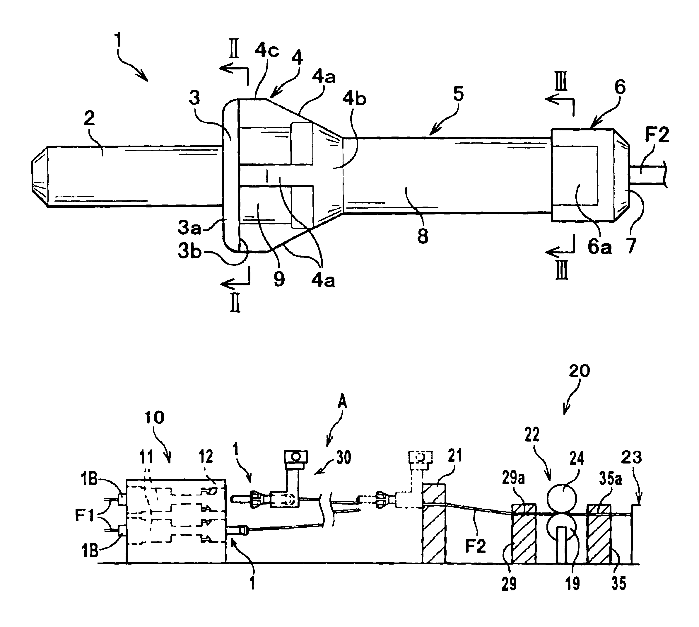
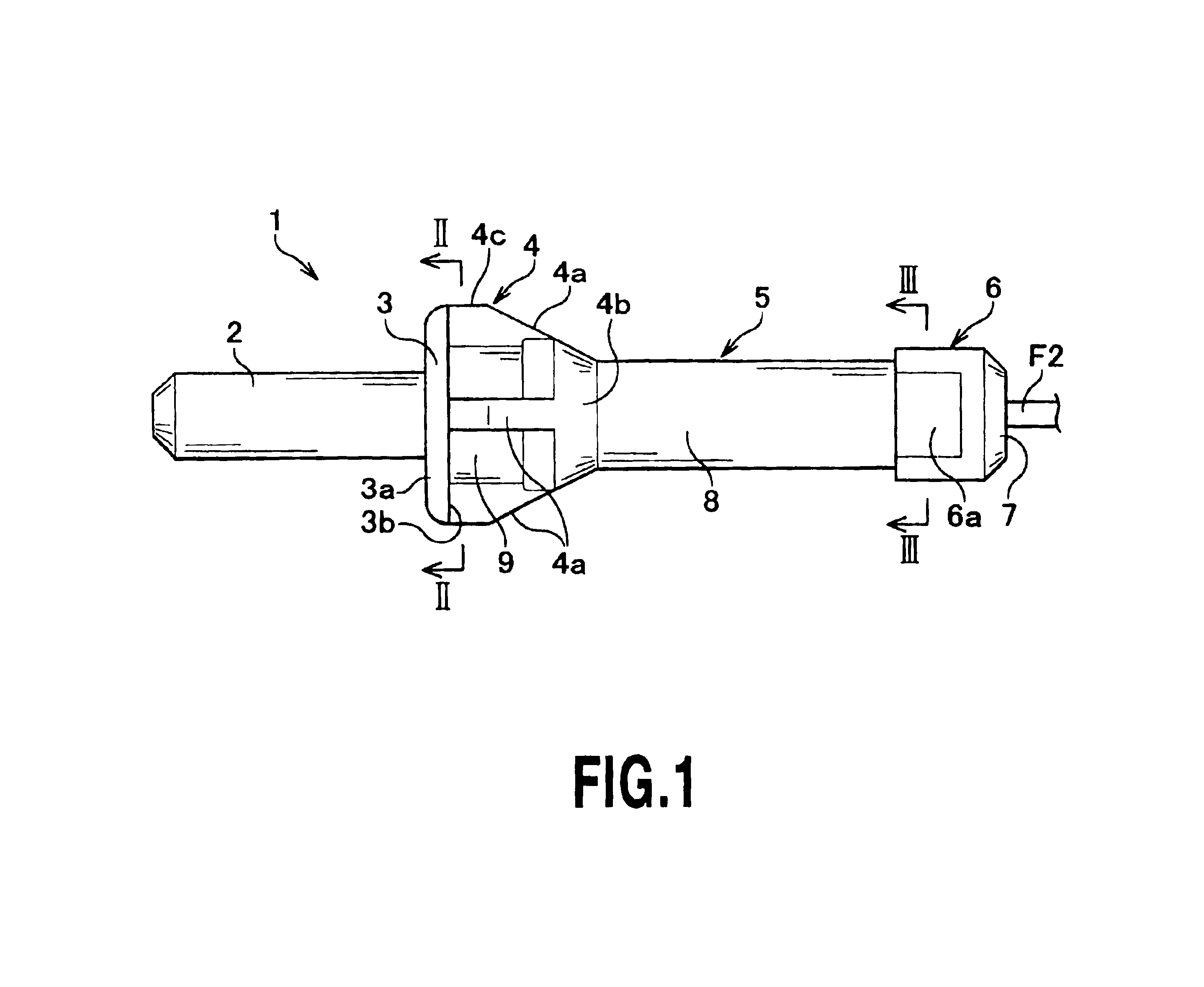
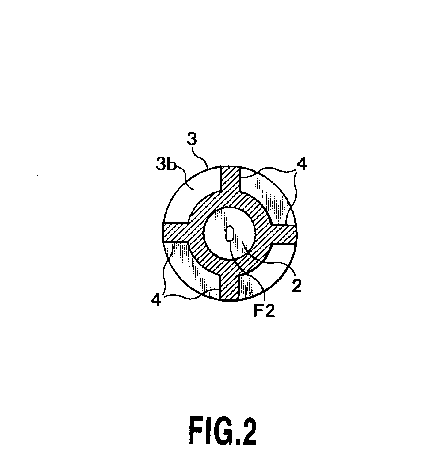
Now, embodiments of the present invention will be described by referring to the accompanying drawings. FIGS. 1 to 3 are a side view of an optical connector plug of this invention as one embodiment and cross-sectional views taken along the lines II—II and III—III. FIG. 4 and FIG. 5 are overall perspective views of the optical connector plug as seen from the front and the rear. FIG. 6 to FIG. 8 are a side view showing the optical connector plug locked by a plug locking hook, a cross-sectional view taken along the line VII—VII and a cross-sectional view similar to FIG. 7 of a plug locking hook in another embodiment. FIG. 9 and FIG. 10 are perspective views of a handling device for holding an optical connector plug in an open state and in a closed state. FIG. 11 to FIG. 13 are overall side views of an optical fiber cross-connection apparatus, with FIG. 11 representing a state in which an operated-side optical connector plug is disconnected from the connection block, FIG. 12 representing...


PUM


Abstract

An optical connector plug according to the present invention which is joined to a front end of an optical fiber cord covering an optical fiber and which is removably inserted to one end of an optical adapter having a locking member for locking the optical connector plug in an engaged state, includes an inserted portion removably inserted to one end of the optical adapter, a plug body joined to a front end of the optical fiber cord, a locking portion formed between the plug body and the inserted portion and locked by the locking member of the optical adapter, and a rotational phase reference surface formed on the plug body away from the locking portion. The optical connector plug according to the present invention can be applied to APC optical connector plug, secure high reliability for optical cross-connecting, and also reduce cost.

Description

This application claims priority from Japanese Patent Application Nos. 2002-255118 filed Aug. 30, 2002 and 2002-267958 filed Sep. 13, 2002, which are incorporated hereinto by reference.BACKGROUND OF THE INVENTION1. Field of the InventionThe present invention relates to an optical connector plug, an optical connector plug connecting method, an optical fiber cross-connection apparatus, an optical fiber cord retracting method, an optical fiber cord retraction device, and an optical connector plug alignment block all used in a cross-connecting operation in an optical network that is performed by automatically connecting or disconnecting optical fibers through the optical connector plugs by using a handling device.2. Description of the Related ArtAn optical fiber cross-connection apparatus connects or disconnects given optical fibers in a group of operated-side optical fibers to and from a group of stationary-side optical fibers. One such optical fiber cross-connection apparatus that aut...

Claims


Application Information

Patent Timeline
Patent Type & Authority Patents(United States)
IPC IPC(8): G02B6/35G02B6/38G02B6/36
CPCG02B6/3807G02B6/3898G02B6/3851G02B6/3893G02B6/3826G02B6/3502G02B6/3574G02B6/3825G02B6/3831G02B6/36
Inventor MIZUKAMI, MASATOSASAKURA, KUNIHIKOKANEKO, KAZUMASAENOMOTO, YOSHITAKA
Owner NIPPON TELEGRAPH & TELEPHONE CORP
Why Eureka
Try Eureka